EasyManua.ls Logo

Mitsubishi Electric PLFY-P20VFM-E1 User Manual

Mitsubishi Electric PLFY-P20VFM-E1
31 pages
To Next Page IconTo Next Page
Page #1 background imageLoading...
Page #1 background image
TECHNICAL & SERVICE MANUAL
Indoor unit
[Model Name] [Service Ref.]
PLFY-P15VFM-E1.TH
PLFY-P20VFM-E1.TH
PLFY-P25VFM-E1.TH
PLFY-P32VFM-E1.TH
PLFY-P40VFM-E1.TH
PLFY-P50VFM-E1.TH
CONTENTS
1. SAFETY PRECAUTION
..........................
2
2. PARTS NAMES AND FUNCTIONS
........
4
3. SPECIFICATIONS
.................................
11
4. 4-WAY AIR FLOW SYSTEM
.................
13
5. OUTLINES AND DIMENSIONS
............
15
6. WIRING DIAGRAM
...............................
16
7.
REFRIGERANT SYSTEM DIAGRAM
......
17
8. TROUBLESHOOTING
..........................
18
9. DISASSEMBLY PROCEDURE
.............
26
PLFY-P15VFM-E1
PLFY-P20VFM-E1
PLFY-P25VFM-E1
PLFY-P32VFM-E1
PLFY-P40VFM-E1
PLFY-P50VFM-E1
Notes:
• This manual describes service data
of the indoor units only.
RoHS compliant products have
<G> mark on spec name plate.
PARTS CATALOG (OCB617)
No. OCH617
March 2016
SPLIT-TYPE, HEAT PUMP AIR CONDITIONERS
R410A
INDOOR UNIT
Model name
indication
Question and Answer IconNeed help?

Do you have a question about the Mitsubishi Electric PLFY-P20VFM-E1 and is the answer not in the manual?

Mitsubishi Electric PLFY-P20VFM-E1 Specifications

General IconGeneral
BrandMitsubishi Electric
ModelPLFY-P20VFM-E1
CategoryAir Conditioner
LanguageEnglish

Summary

SAFETY PRECAUTION

CAUTIONS RELATED TO NEW REFRIGERANT

Cautions for units utilizing R410A refrigerant, handling tools, and general safety.

PARTS NAMES AND FUNCTIONS

Indoor Unit Components

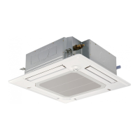
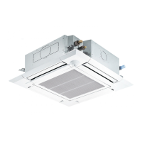
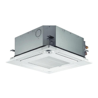
Identifies and describes the function of key parts of the indoor unit.

Wired Remote Controller Operation

Details the functions and operation of the wired remote controller.

Wireless Remote Controller Overview

Explains the operation and functions of the wireless remote controller.

SPECIFICATIONS

General Unit Specifications

Provides technical specifications for various indoor unit models.

Electrical Parts Specifications

Lists the electrical components and their specifications for the indoor units.

4-WAY AIR FLOW SYSTEM

Fresh Air Intake and Duct Fan Operation

Details fresh air intake, characteristics, and operation with a duct fan.

Fixing Horizontal Vane

Describes the procedure for fixing the horizontal vane of the air outlet.

OUTLINES AND DIMENSIONS

Unit Dimensions and Installation Clearances

Provides detailed dimensions and required installation spaces for the indoor units.

WIRING DIAGRAM

Indoor Unit Wiring Diagram

Illustrates the electrical connections and component layout for the indoor units.

REFRIGERANT SYSTEM DIAGRAM

Refrigerant Circuit Overview

Shows the flow of refrigerant through the indoor unit components.

TROUBLESHOOTING

Error Code Countermeasures

Lists error codes and their corresponding countermeasures during test runs.

Component Checking Procedures

Guides on how to check the functionality of various internal parts using a tester.

DC Fan Motor Troubleshooting

Provides a troubleshooting flowchart for the DC fan motor and controller board.

Dip Switch Functions

Explains the functions and settings of the DIP switches on the control board.

Test Point Diagram for Controller Board

Identifies test points on the indoor controller board for troubleshooting.

DISASSEMBLY PROCEDURE

Panel and Internal Component Removal

Step-by-step guide on how to remove panels and internal parts of the unit.

Thermistor and Fan Motor Removal

Instructions for removing thermistors and the fan motor.

Drain Pump and Heat Exchanger Removal

Procedures for removing the drain pump and heat exchanger.

Related product manuals