EasyManua.ls Logo

Mitsubishi Electric PLFY-P08NFMU-E User Manual

Mitsubishi Electric PLFY-P08NFMU-E
32 pages
To Next Page IconTo Next Page
Page #1 background imageLoading...
Page #1 background image
Indoor unit
[Model Name] [Service Ref.]
PLFY-P05NFMU-E.TH
PLFY-P08NFMU-E.TH
PLFY-P12NFMU-E.TH
PLFY-P15NFMU-E.TH
PLFY-P18NFMU-E.TH
PLFY-P05NFMU-E
PLFY-P08NFMU-E
PLFY-P12NFMU-E
PLFY-P15NFMU-E
PLFY-P18NFMU-E
R410A
TECHNICAL & SERVICE MANUAL
March 2018
Notes:
7KLs PDQXDO GesFULEes seUYLFe
GDtD oI tKe LQGooU XQLts oQO\
5o+6 FoPSOLDQt SUoGXFts
KDYe *! PDUN oQ sSeF
QDPe SODte
63/,77<3( +($7 3803 $,5 &2N',7,2N(56
No. OCH604
REVISED EDITION-A
5eYLsLoQ:
0oGLILeG LQ :$< $,5
)/2: 6<67(0 LQ 5(9,6('
(',7,2N$
6oPe GesFULStLoQs KDYe EeeQ
PoGLILeG
2&+ Ls YoLG
INDOOR UNIT
0oGeO QDPe
LQGLFDtLoQ
CONTENTS
1. SAFETY PRECAUTION
..........................
2
2. PARTS NAMES AND FUNCTIONS
........
4
3. SPECIFICATIONS
.................................
12
4. 4-WAY AIR FLOW SYSTEM
.................
14
5. OUTLINES AND DIMENSIONS
............
16
6. WIRING DIAGRAM
...............................
17
7.
REFRIGERANT SYSTEM DIAGRAM
......
18
8. TROUBLESHOOTING
..........................
19
9. DISASSEMBLY PROCEDURE
.............
27
PARTS CATALOG (OCB604)
Question and Answer IconNeed help?

Do you have a question about the Mitsubishi Electric PLFY-P08NFMU-E and is the answer not in the manual?

Mitsubishi Electric PLFY-P08NFMU-E Specifications

General IconGeneral
BrandMitsubishi Electric
ModelPLFY-P08NFMU-E
CategoryAir Conditioner
LanguageEnglish

Summary

1. SAFETY PRECAUTION

R410A Refrigerant Safety

Discusses safety precautions for R410A refrigerant, handling, and piping.

2. PARTS NAMES AND FUNCTIONS

2-1. Indoor Unit

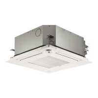
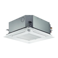
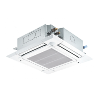
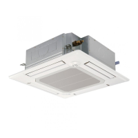
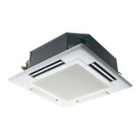
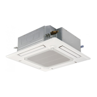
Details the components and functions of the indoor unit.

2-2. Wired Remote Controller <PAR-32MAA>

Explains the functions and features of the PAR-32MAA wired remote controller.

2-2-2. Wired Remote Controller <PAC-YT53CRAU>

Details the functions and display of the PAC-YT53CRAU wired remote controller.

2-3. Wireless remote controller

Describes the operation and features of the wireless remote controller.

3. SPECIFICATIONS

3-1. General Specifications

Provides detailed technical specifications for various indoor unit models.

3-2. Electrical Parts Specifications

Lists electrical components and their specifications for the indoor units.

4. 4-WAY AIR FLOW SYSTEM

4-1. FRESH AIR INTAKE

Details the location and installation of the fresh air intake duct.

4-2. FRESH AIR INTAKE AMOUNT & STATIC PRESSURE CHARACTERISTICS

Presents data curves for fresh air intake amount and static pressure.

4-3. OPERATION IN CONJUNCTION WITH DUCT FAN (Booster fan)

Explains how to operate the indoor unit with an external duct fan.

4-4. FIXING HORIZONTAL VANE

Describes the procedure for manually setting the horizontal vane position.

5. OUTLINES AND DIMENSIONS

6. WIRING DIAGRAM

7. REFRIGERANT SYSTEM DIAGRAM

8. TROUBLESHOOTING

8-1. COUNTERMEASURES FOR ERROR DURING TEST RUN

Lists error codes and corresponding countermeasures during system test runs.

8-2. HOW TO CHECK THE PARTS

Provides methods for checking the resistance and functionality of various parts.

8-2-1. Thermistor Characteristic Graph

Shows the resistance-to-temperature relationship for thermistors.

8-2-2. Linear Expansion Valve

Details the operation and connection of the linear expansion valve.

Linear Expansion Valve Troubleshooting

Discusses troubleshooting steps for linear expansion valve issues and pulse signals.

8-2-3. DC Fan Motor (Fan Motor/Indoor Controller Board)

Guides on checking the DC fan motor and indoor controller board for issues.

8-3. FUNCTION OF DIP SWITCH

SW1-SW14 DIP Switch Functions

Details the functions of various DIP switches for system configuration and settings.

SW21 & SW22 Function Selection

Covers function selection for SW21 (fan speed, height) and SW22 (remote pairing).

SWE Test Run Function

Describes the SWE switch for activating the drain pump test run.

8-4. TEST POINT DIAGRAM

9. DISASSEMBLY PROCEDURE

Air Intake Grille, Filter, and Panel Removal

Covers removing the air intake grille, filter, and main unit panel.

Removing Electrical Parts

Details removing electrical parts like thermistors, drain pump, and control box components.

Removing Fan Motor and Heat Exchanger

Guides on disassembling the fan motor, heat exchanger, and associated parts.

Removing Drain Pump and Float Switch

Steps to remove the drain pump and float switch.

Related product manuals