Do you have a question about the Mitsubishi Electric PLH Series and is the answer not in the manual?
| Brand | Mitsubishi Electric |
|---|---|
| Model | PLH Series |
| Category | Air Conditioner |
| Language | English |
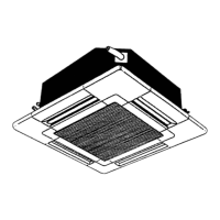
Identifies and explains the parts of the indoor unit, including outlets, filters, and intake.
Explains the buttons and display functions of the remote controller for operating the unit.
Lists specifications for the indoor unit, including capacity, power supply, dimensions, and weight.
Provides specifications for the outdoor unit, covering power, refrigerant control, compressor, and heat exchanger.
Details specifications for refrigerant piping, including pipe size, connection method, and length limits.
Lists cooling capacities and power consumption under various indoor/outdoor conditions.
Provides heating capacities and power consumption data for different operating conditions.
Details the dimensions, ceiling hole requirements, and installation clearances for the indoor unit.
Shows diagrams illustrating the dimensions and mounting points for the outdoor unit.
Details the wiring connections between the indoor unit controller and the remote controller.
Shows the electrical connections required for the outdoor unit, including power supply and unit interface.
Shows the refrigerant circuit for PLH-3GK(H)B1.UK indoor and PUH-3VKA2.UK/PUH-3YKA2.UK outdoor units.
Illustrates the refrigerant flow for PLH-4GK(H)SB1.UK indoor and PUH-4YKSA2.UK outdoor units.
Details the refrigerant system for PLH-5GK(H)SB1.UK indoor and PUH-5YKSA2.UK outdoor units.
Depicts the refrigerant circuit for PLH-6GK(H)SB1.UK indoor and PUH-6YKSA2.UK outdoor units.
Outlines the primary operational flow of the air conditioning system from start to stop.
Details the step-by-step process and conditions for the cooling operation mode.
Illustrates the operational logic and control sequence for the dry operation mode.
Shows the process flow and logic for the heating operation mode.
Explains the automatic mode switching between cooling and heating based on temperature.
Provides an overview of the microprocessor control system, inputs, outputs, and components.
Describes the indoor unit's control logic during cooling operation, including fan and compressor control.
Explains the control functions for the indoor unit during dry operation mode.
Details the control logic for the indoor unit during heating operation, including fan and heater control.
Describes the automatic switching logic between cooling and heating modes based on room temperature.
Explains how to adjust and control the auto vane direction for optimal airflow.
Explains how the outdoor fan speed is controlled based on outdoor coil temperature.
Describes how the outdoor unit responds to commands from the indoor unit for cooling/heating.
Outlines the protective functions that stop operation and display error codes when abnormalities occur.
Illustrates the timing sequence for compressor, heater, and valve operations during COOL/HEAT modes.
Explains the conditions and process for defrosting operation during heating mode.
Describes the operation of bypass valves and crankcase heaters under various conditions.
Details special service functions like compulsory defrosting, fixed fan output, and switch functions.
Lists common symptoms and causes for problems during the test run phase.
Explains how to use the self-diagnostic function to identify malfunctions via the remote controller.
Describes how to use switches on the outdoor controller board to indicate service data and check codes.
Provides a cross-reference table for check codes and corresponding troubleshooting steps.
Offers troubleshooting steps for scenarios where the outdoor unit fails to operate.
Guides on selecting airflow patterns and adjusting air outlets based on ceiling height and unit configuration.
Explains the procedure for adjusting the width of air outlets for full opening or closing.
Provides instructions for installing fresh air intake duct flanges and related components.
Details the process of installing branch ducts for multi-directional airflow and their static pressure characteristics.
Lists different control system options, including single remote, dual remote, and group control.
Explains how to set up and operate multiple units using a single remote controller.
Details how to use two remote controllers for managing units individually or in groups.
Describes methods for remote ON/OFF switching and individual unit control using relays and adapters.
Explains how to achieve individual control by grouping remote controllers without a special control board.
Details the use of a multiple remote control display for monitoring and operating multiple units.
Explains the auto restart function that restores operation after a power failure.
Details the specifications and connection methods for optional refrigerant pipe kits.
Describes the program timer and its specifications for scheduling operations.