Do you have a question about the Mitsubishi Electric PQHY-P200YLM-A and is the answer not in the manual?
| Brand | Mitsubishi Electric |
|---|---|
| Model | PQHY-P200YLM-A |
| Category | Air Conditioner |
| Language | English |
Check refrigerant type, symptoms, safety precautions, and prepare necessary tools before servicing.
Lists the essential tools and materials for installation and servicing, categorizing them by R410A exclusivity.
Details copper pipe materials, types, radial thickness, and radial thickness specifications for R410A systems.
Guidelines for storing piping indoors and sealing pipe ends to prevent contamination and moisture.
Instructions for performing brazing, emphasizing non-oxidized solder and avoiding foreign objects.
Details on performing air tightness tests using nitrogen, emphasizing R410A must be charged in liquid state.
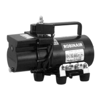
Explains the use of vacuum pumps with check valves, vacuum gauge precision, and evacuation time.
Guidelines for refrigerant charging, emphasizing liquid phase charging for R410A and cylinder color.
Procedures for replenishing refrigerant after a leak, referring to specific sections for detailed guidance.
Compares chemical properties, safety class, pressure, and charging methods of R410A and conventional refrigerants.
Details on refrigerating machine oil for HFC systems, effects of contaminants, and oil degradation causes.
Safety guidelines for servicing, including handling control boxes, high-voltage parts, and tightening torques.
Summarizes compatible indoor units for various heat source units and maximum total capacity.
Specifies cable types and maximum allowable lengths for transmission and remote controller wiring.
Details switch settings on various units and the M-NET address settings table for system configuration.
Illustrates typical system connections for MA remote controllers, ME remote controllers, and combined systems.
Provides guidelines on total pipe length, height difference, and pipe sections for various models.
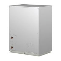
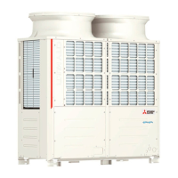
Illustrates the front view of heat source units and describes components within the refrigerant circuit.
Details the components within the control box, including safety warnings and internal layout.
Provides a detailed view of the heat source unit control board, highlighting connectors and switches.
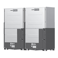
Illustrates the front and rear views of BC controller components, identifying key parts like sensors and valves.
Shows the internal layout of the BC controller control box, including transformer, relay, and BC boards.
Details the BC controller circuit board, labeling connectors for various signals and components.
Compares functions and specifications of MA and ME remote controllers and provides selection criteria.
Explains how to perform group operations and interlock settings for LOSSNAY units using the ME remote controller.
Details the procedure for setting LOSSNAY interlocks using the MA remote controller (PAR-31MAA).
Explains how to select temperature detection position, setting SW1-1 on the indoor unit controller board.
Provides the electrical wiring diagram for the heat source unit, including component and terminal block details.
Illustrates the electrical wiring for the BC controller, detailing component connections and switch settings.
Shows the electrical wiring diagram for the transmission booster, including component connections.
Presents schematic diagrams of the refrigerant circuit for various heat source unit models.
Details the principal parts of the heat source unit and their functions, including symbols and specifications.
Explains the functions and factory settings of dipswitches on the control board and INV board.
Describes the control method for heat source units, including startup sequence and initial control.
Details the control functions for solenoid valves, SVM, and LEV within the BC controller.
Provides flowcharts illustrating mode determination for indoor units and heat source units.
Lists essential checks before initiating a test run, including refrigerant leaks and electrical connections.
Provides step-by-step instructions for performing a test run using the MA remote controller.
Explains refrigerant characteristics and operating parameters important for adjusting refrigerant amount.
Guides on adjusting refrigerant amount based on symptoms and operating conditions.
Details the procedures for adding or extracting refrigerant using the SW4 No.922 switch.
Lists symptoms that are considered normal during unit operation, along with their causes.
Provides reference data for standard operation parameters for various heat source unit models.
Comprehensive list of error codes, their definitions, and searched units for troubleshooting.
Provides guidance on how to respond to error displays on the remote controller.
Explains how to investigate transmission wave patterns and noise interference on M-NET lines.
Guides on troubleshooting specific parts like pressure sensors, solenoid valves, and LEV components.
Details procedures for identifying and repairing refrigerant leaks in extension pipes and heat source units.
Step-by-step procedures for removing and replacing compressor components and reassembly.
Provides instructions for replacing water-cooled heat exchanger assembly parts and precautions for brazing.
Guides on servicing the BC controller, including removal of service panels and control box components.
Explains how to read LED error displays on the heat source unit board and provides troubleshooting steps.