Do you have a question about the Mitsubishi Electric CITY MULTI PQRY-P200YMF-B and is the answer not in the manual?
| Series | CITY MULTI |
|---|---|
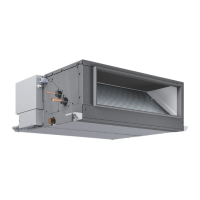
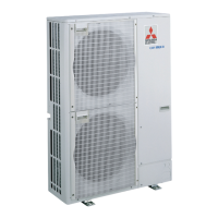
| Type | Outdoor Unit |
| Cooling Capacity | 20.0 kW |
| Heating Capacity | 22.4 kW |
| Refrigerant | R410A |
| Power Supply | 380-415V, 50Hz, 3-Phase |
| Operating Temperature (Cooling) | -5°C to 46°C |
| Operating Temperature (Heating) | -15°C to 24°C |
Guidelines for storing refrigerant piping materials indoors to prevent contamination.
Proper use of oils and tools for piping connections to prevent contamination.
Lists required tools and materials for R407C, highlighting differences from R22.
Emphasizes non-oxide brazing and clean connections to prevent circuit contamination.
Details the nitrogen pressurization method for checking system airtightness.
Specifies requirements for vacuum pumps and gauges for effective system evacuation.
Instructions for charging R407C in liquid state due to its non-azeotropic nature.
Guidelines for replacing the dryer when the refrigerant circuit is opened.
Essential safety checks and warnings before commencing installation or electrical work.
Explains symbols used to indicate warnings and cautions in the manual.
Explains symbols used in diagrams and illustrations for actions and warnings.
Identifies major components within the heat source unit, such as compressors and heat exchangers.
Illustrates the refrigerant flow and location of thermal sensors within the system.
Details the system configuration, including heat source units, BC controllers, and indoor units.
Provides a detailed electrical schematic for the heat source unit.
Presents standard operating data for cooling mode, including temperatures and pressures.
Presents standard operating data for heating mode, including temperatures and pressures.
Explains the functions of DIP switches and rotary switches on the heat source unit.
Details DIP switch settings for various indoor unit functions and models.
Explains DIP switch settings for the BC controller unit.
Describes output signals like operation ON signal and COMP ON/OFF signal.
Details input signals such as Pump Interlock and Demand.
Lists critical checks and cautions before performing a test run.
Checks to perform for test runs with specific optional parts installed.
Specific installation and wiring checks for drain water lifting-up mechanisms.
Checks for correct system structure related to installation and piping.
Checks related to proper power source wiring and grounding.
Explains the need for switch operations to set unit addresses and connection numbers.
Details address setting procedures and switch operations for single and group systems.
Details the functions of various switches used for registering indoor units with a remote controller.
Explains the unit attribute display during group registration and information retrieval.
Outlines operations for group registration, retrieval, and deletion of unit information.
Procedures to retrieve and confirm group registration information and unit registration details.
Details the control logic for the heat source unit, including initial processing and starting.
Explains the function of bypass solenoid valves (SV1, SV2) for capacity control.
Describes how frequency control maintains evaporation and saturation temperatures.
Explains how high pressure limits affect frequency reduction.
Details how discharge temperature limits trigger frequency reduction.
Describes the periodic adjustment of frequency for optimal performance.
Explains how SLEV opening is controlled based on compressor frequency and ambient temperature.
Describes the control of the liquid level heater based on frequency and outdoor air temperature.
Explains how refrigerant amount is judged and controlled based on accumulator liquid level.
Details the control systems for heat source unit fans and heat exchanger capacity.
Explains the control logic for the cooling fan within the control box.
Details the control method for LEV 2, including pulse signals and valve opening.
Explains the ON/OFF control of solenoid valves SVA, SVB, and SVC based on connection mode.
Details the ON/OFF control of SVM based on the operation mode.
Explains how LEV opening is controlled corresponding to operation mode and conditions.
Provides a flowchart illustrating the operational sequence of the heat source unit.
Presents a flowchart detailing the operational sequence of the BC controller.
Illustrates the operational flow for an indoor unit, including error conditions and prohibitions.
Flowchart detailing the sequence of operations during cooling mode.
Flowchart outlining the operational sequence for heating mode.
Flowchart illustrating the operational sequence for dry mode.
Details the function, application, and specifications of the compressor.
Describes the function of the high pressure sensor for detection and protection.
Describes the function of the low pressure sensor for detection and configuration.
Details the function of the pressure switch for high and low pressure detection.
Explains the function of TH1 thermistor for discharge temperature and overheat protection.
Describes the function of TH2 thermistor for saturated vapor temperature and control.
Explains the function of TH3 and TH4 thermistors for liquid level detection.
Describes the function of TH6 thermistor for inlet water temperature and oil return.
Explains the function of TH9 thermistor for CS circuit temperature and refrigerant circulation.
Describes the function of THINV thermistor for inverter cooler heat exchanger outlet temperature.
Explains the function of TH10 thermistor for compressor shell temperature.
Details the function of SV1 and SV2 solenoid valves for bypass and capacity control.
Explains the function of SV3-6 and SV71-73 solenoid valves for heat exchanger capacity control.
Describes the function of SLEV for liquid refrigerant return.
Details the function of LEV2 for controlling inverter cooler refrigerant flow.
Explains the function of CH2 and CH3 for accumulator liquid level detection.
Describes the function of LEV for adjusting heat source unit superheat.
Details the function of PS1 and PS3 pressure sensors for liquid pressure and intermediate detection.
Explains the function of TH11-TH16 thermistors for LEV control.
Details the function of SVM, SVA, SVB, SVC solenoid valves for unit operation and refrigerant supply.
Describes the function of LEV1 and LEV3 for liquid level and pressure control.
Clarifies the relationship between refrigerant amount and operating characteristics.
Details the process of adjusting and judging the refrigerant amount.
Details the process of adjusting and judging the refrigerant amount.
Details the process of adjusting and judging the refrigerant amount.
Step-by-step procedure for adjusting refrigerant amount in cooling and heating modes.
Step-by-step procedure for adjusting refrigerant amount in cooling and heating modes.
Step-by-step procedure for adjusting refrigerant amount in cooling and heating modes.
Details major components and their troubleshooting procedures.
Details major components and their troubleshooting procedures.
Details major components and their troubleshooting procedures.
Explains how pulse signals control LEV valve opening and closing.
Graph illustrating the relationship between pulse count and valve opening angle.
Explains LEV operation via pulse signals from the microcomputer.
Details pulse signal output states for LEV valve operation.
Illustrates valve closing and opening operations and related sounds.
Identifies driver circuit failure and suggests replacing the control board.
Describes locked LEV mechanisms and suggests replacing the LEV.
Addresses issues with LEV motor coils and suggests replacing coils.
Explains fully closed valve leaks and suggests replacing the LEV if leakage is significant.
Addresses faulty wire connections and suggests checking continuity.
Lists symptoms and error codes related to transmission line noise.
Explains how to use an oscilloscope to check transmission line wave shape and voltage levels.
Lists checks and measures to take against noise affecting transmission lines.
Outlines checks and measures when wave height is low, or 6607 error occurs.
Important cautions for measuring inverter power circuit voltages and currents.
Lists items to check when troubleshooting breaker tripping issues.
Procedures for checking after powering the unit again.
Steps for operational checks, including normal operation and breaker tripping scenarios.
Method for judging failure of the diode stack.
Method for judging failure of the transistor module.
Method for measuring resistance to judge failure of the contactor.
Method for measuring resistance of rush current protection resistors.
Method for measuring resistance of the DC reactor.
Method for measuring resistance of the cooling fan.
Method for measuring resistance of the transformer.
Important cautions regarding the replacement of inverter parts.
Troubleshooting flow for pressure sensors, including checking connections and readings.
Troubleshooting flow for pressure sensors, including checking connections and readings.
Details connector correspondence, resistance measurement, graphs, and LED monitor checks.
Lists symptoms of incorrect connection to the BC controller LEV board.
Procedures to check LEV full open/closed status using LED monitor and pressure differential.
Table detailing LEV opening characteristics based on differential pressure and superheat control.
Explains the ON/OFF coordination of SVA, SVB, SVC with operation modes.
Details the ON/OFF coordination of SVM with operation modes.
Instructions for measuring piping temperatures at specific points for SVA, SVB, and SVM.
Step-by-step instructions for removing the service panel of the BC controller.
Procedures for accessing and checking components within the BC controller's control box.
Troubleshooting steps for mechanical issues identified by check codes, starting with serial transmission abnormality.
Troubleshooting steps for mechanical issues identified by check codes, starting with serial transmission abnormality.
Troubleshooting steps for mechanical issues identified by check codes, starting with serial transmission abnormality.
Troubleshooting steps for mechanical issues identified by check codes, starting with serial transmission abnormality.
Troubleshooting steps for mechanical issues identified by check codes, starting with serial transmission abnormality.
Troubleshooting steps for mechanical issues identified by check codes, starting with serial transmission abnormality.
Troubleshooting steps for mechanical issues identified by check codes, starting with serial transmission abnormality.
Troubleshooting steps for mechanical issues identified by check codes, starting with serial transmission abnormality.
Troubleshooting steps for mechanical issues identified by check codes, starting with serial transmission abnormality.
Troubleshooting steps for mechanical issues identified by check codes, starting with serial transmission abnormality.
Troubleshooting steps for mechanical issues identified by check codes, starting with serial transmission abnormality.
Troubleshooting steps for mechanical issues identified by check codes, starting with serial transmission abnormality.
Troubleshooting steps for mechanical issues identified by check codes, starting with serial transmission abnormality.
Troubleshooting steps for mechanical issues identified by check codes, starting with serial transmission abnormality.
Troubleshooting for communication and system errors, starting with multiple address errors.
Troubleshooting for communication and system errors, starting with multiple address errors.
Troubleshooting for communication and system errors, starting with multiple address errors.
Troubleshooting for communication and system errors, starting with multiple address errors.
Troubleshooting for communication and system errors, starting with multiple address errors.
Troubleshooting for communication and system errors, starting with multiple address errors.
Troubleshooting for communication and system errors, starting with multiple address errors.
Guide on interpreting service LED displays on the control circuit board using DIP switches.
Explains the meaning of E2, M, and E* indicators in the LED monitor display.
Procedure for locating leaks in extension piping or indoor units during cooling.
Procedure for locating leaks in the heat source unit during cooling mode.
Procedure for locating leaks in extension piping or indoor units during heating.
Procedure for locating leaks in the heat source unit during heating.
Notes on unit stabilization, checking αOC ranges, troubleshooting sensors, refrigerant charging, and calibration.
Compares chemical and physical properties of R407C with R22.
Explains how refrigerant composition changes if leaks occur or if charged incorrectly.
Notes the use of different refrigerator oil for HFC-based refrigerants than R22.
Details the impact of contaminants like moisture, air, and dirt on the refrigeration cycle and oil.