Do you have a question about the Mitsubishi Electric CITY MULTI PUHY-P108 and is the answer not in the manual?
| Model | PUHY-P108 |
|---|---|
| Category | Air Conditioner |
| Series | CITY MULTI |
| Cooling Capacity | 10.8 kW |
| Refrigerant | R410A |
| Sound Pressure Level (Outdoor Unit) | 58 dB(A) |
| Weight (Outdoor Unit) | 130 kg |
| Power Supply | 208-230V, 60Hz, 3-Phase |
| Indoor Unit Compatibility | CITY MULTI Indoor Units |
| Operating Temperature (Cooling) | -5°C to 46°C |
| Operating Temperature (Heating) | -20°C to 15.5°C |
Lists essential tools and materials for installing and servicing the units.
Details copper pipe specifications, types, and radial thickness requirements for R410A.
Procedures and items to observe for proper brazing to prevent foreign objects from entering the system.
Explains the procedure for vacuum drying the system to remove moisture and achieve the required vacuum degree.
Compares chemical properties, composition, pressure, and other characteristics of R410A with conventional refrigerants.
Specifies cable types and maximum transmission distances for M-NET and remote controller wiring.
Details the need for switch settings and the ranges of address settings for various units and controllers.
Outlines the allowable lengths for refrigerant pipes based on configuration and height differences.
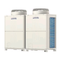
Shows the appearance and components of PUHY-P72, P96, and P108 outdoor models.
Details the internal components within the outdoor unit's control box for PUHY/PURY series.
Provides a detailed layout of the outdoor MAIN board, showing connector and component locations.
Compares functions and specifications of MA and M-NET (ME) remote controllers for system selection.
Guides on performing group operations and interlock settings using the M-NET (ME) remote controller.
Details the procedure for setting LOSSNAY interlocks with indoor units using the MA remote controller.
Provides wiring diagrams for PUHY-P72, P96, 108, P126, and P144 outdoor models.
Presents electrical wiring diagrams for various BC controller models.
Illustrates the refrigerant circuit for PUHY-P72, P96, and P108 outdoor units.
Lists and explains the function of key components like compressors, sensors, and valves.
Details the functions and factory settings of DIP switches on the outdoor unit main board.
Explains initial control, start-up control, and bypass control for PUHY/PURY outdoor units.
Describes the control logic for solenoid valves and LEV based on operation modes.
Lists essential checks before performing a test run, including insulation resistance and valve status.
Provides a step-by-step guide on how to perform a test run using the MA deluxe remote controller.
Explains how to adjust refrigerant amount based on symptoms and operational data.
Lists error codes, their definitions, and the units where they can occur.
Provides causes and remedies for specific error codes displayed on the remote controller.
Details procedures for locating and repairing refrigerant leaks in cooling and heating seasons.
Explains how to interpret numerical and flag displays on the service monitor's 7-segment LEDs.