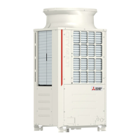
Do you have a question about the Mitsubishi Electric CITY MULTI PUHY-P200YEM-A and is the answer not in the manual?
| Brand | Mitsubishi Electric |
|---|---|
| Model | CITY MULTI PUHY-P200YEM-A |
| Category | Air Conditioner |
| Language | English |
Guidelines for proper storage of refrigerant piping materials to prevent contamination and damage.
Instructions for preparing and machining refrigerant piping, including oil application and quantity.
Guidelines for charging R407C refrigerant in liquid state, including cylinder identification and methods.
Detailed electrical wiring diagram for PU(H)Y-(P)YEM(K,C)-A models, showing connections and components.
Electrical wiring diagram for PURY-P200/250YEM-A models, illustrating system wiring and component connections.
Details on the function of DIP switches (SWU, SW1, SW2, SW3, SW4) for the outdoor unit and their settings.
Checkpoints and cautions to be observed before performing a test run on the unit.
Specific safety warnings and procedures for checking the high-voltage inverter section of the outdoor unit.
Step-by-step procedure for conducting a test run, including button presses and checks for air flow and temperature.
Procedure for registering indoor units with the remote controller for group operation.
Details on outdoor unit control, including initial processing, starting control, and bypass/capacity control.
Explanation of the control logic for SVA, SVB, SVC solenoid valves and LEV opening based on operation mode.
Key relationships between refrigerant amount and system performance characteristics for accurate adjustment.
Methods for diagnosing and adjusting refrigerant levels based on symptoms and self-diagnosis.
Step-by-step procedure for operating the refrigerant volume adjustment mode using outdoor unit switches.
Identification and troubleshooting of major system components like pressure sensors and their configurations.
Troubleshooting steps and countermeasures for various inverter output errors and related component issues.
Procedures for diagnosing and resolving issues when the main power breaker trips, including inverter circuit checks.
List of intermittent fault codes and their preliminary error contents for diagnosing system issues.
Procedure for locating refrigerant leaks in extension piping or indoor units during cooling mode operation.
Steps to locate refrigerant leaks in the outdoor unit during cooling mode operation.
Procedure for locating refrigerant leaks in extension piping or indoor units during heating mode operation.
Steps to locate refrigerant leaks in the outdoor unit during heating mode operation.


 Loading...