Do you have a question about the Mitsubishi Electric CITY MULTI PUHY-80TMU-A and is the answer not in the manual?
| Brand | Mitsubishi Electric |
|---|---|
| Model | CITY MULTI PUHY-80TMU-A |
| Category | Air Conditioner |
| Language | English |
Important safety points for installation and electrical work.
Explains symbols used for warnings and cautions in the text.
Explains symbols used in diagrams and illustrations for safety.
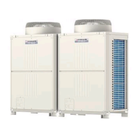
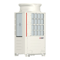
Illustrates the external appearance and major parts of the outdoor unit.
Details the internal components of the rear controller box.
Shows the layout and connections of the main control board.
Illustrates the inverter board and its connectors/components.
Shows the Gate Amplifier board and its components.
Displays the power board with its major components.
Detailed diagram of the refrigerant circuit and thermal sensor locations.
Provides the complete electrical wiring diagram for the models.
Lists major components and their functions for troubleshooting.
Explains how to use self-diagnosis switches and interpret LED indicators.
Presents standard operational data for cooling and heating modes.
Presents standard operational data for cooling mode.
Presents standard operational data for heating mode.
Details the functions of various switches for configuration.
Details the functions of DIP switches and rotary switches for the outdoor unit.
Explains the functions of DIP switches for the indoor unit.
Configuration details for DIP switches SW4 and SW5.
Core procedure for testing unit functionality.
Lists essential checks to perform before initiating a test run.
Provides step-by-step instructions for conducting a test run.
Verifies system structure and installation for proper operation.
Verifies installation and piping for proper system operation.
Ensures correct power source wiring for the system.
Validates transmission line and system setup parameters.
Final checks before starting the system operation.
Procedures for registering and managing indoor units with M-NET controller.
Explains the function of various switches for registration.
Describes how unit types are displayed during registration.
Details operations for registering, deleting, and retrieving unit information.
Procedures for retrieving and confirming registered unit information.
Steps for deleting registered indoor unit information.
Process for deleting non-existent addresses and associated data.
Explains the operational logic and control mechanisms of the unit.
Explains the control logic for the outdoor unit operations.
Visual representation of outdoor unit operation modes.
Details how bypass and capacity are controlled.
How frequency is managed for capacity and temperature control.
Manages oil return using electronic expansion valves.
Controls the subcool coil using an electronic expansion valve.
Details the logic for defrosting operations.
Guides on adjusting and managing refrigerant amount for optimal performance.
Relates refrigerant amount to operating characteristics.
Guides on adjusting and judging the refrigerant amount.
Steps for operating in refrigerant volume adjustment mode.
Detailed method for adjusting refrigerant volume.
Lists major components and their functions for troubleshooting.
A comprehensive list of error codes and their meanings.
Diagnosing issues based on check codes and implementing countermeasures.
Troubleshooting mechanical components, sensors, and pressure issues.
Addresses issues related to the low pressure saturation temperature sensor.
Troubleshoots high pressure issues in the outdoor unit.
Further troubleshooting for high pressure issues in the outdoor unit.
Identifies and resolves issues related to refrigerant overcharging.
Addresses problems related to suction pressure.
Troubleshoots water leaks, drain pump, sensor, and float switch problems.
Addresses open phase and reverse phase errors in power supply.
Troubleshoots power supply sync signals and fan motor problems.
Diagnoses issues with the VDC sensor and its circuit.
Addresses bus voltage issues and radiator overheat protection.
Troubleshoots overcurrent and breaking protection errors.
Diagnoses cooling fan and IDC sensor/circuit problems.
Addresses errors related to various sensors and pressure readings.
Addresses communication and system-level errors.
Troubleshoots multiple address and transmission processor hardware errors.
Addresses errors related to transmission circuit bus busy status.
Diagnoses communication errors with the transmission processor.
Troubleshoots No ACK errors in communication.
Interpreting LED indicators for system status and errors.
Explains the meaning of LED indicators and their displays.


 Loading...