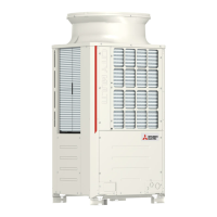
Do you have a question about the Mitsubishi Electric City Multi PUHY-P120TKMU-A and is the answer not in the manual?
| Brand | Mitsubishi Electric |
|---|---|
| Model | City Multi PUHY-P120TKMU-A |
| Category | Air Conditioner |
| Language | English |
Guidance on actions to take before commencing installation and electrical work.
Covers crucial safety measures for installation, handling, and operation to prevent injury or damage.
Specific safety guidelines for handling R410A refrigerant and related equipment.
Important considerations and warnings before proceeding with unit installation.
Specific electrical work precautions for unit relocation and installation.
Essential checks and preparations before initiating the unit's test run.
Provides general information about the product and its refrigerant type.
Information on compatible combinations of outdoor and indoor units.
Tables detailing compatible outdoor and indoor unit model combinations.
Technical specifications for various models, including sound, capacity, and operating temperatures.
Detailed specifications for outdoor units, covering sound, pressure, capacity, and operating ranges.
List of components supplied with the unit.
List of parts included in the package with their respective quantities.
Guidelines on necessary clearances for unit installation and operation.
Diagrams and dimensions for required space around a single unit.
Space requirements for multiple units installed adjacently (side-by-side, face-to-face, combined).
Instructions and precautions for safely transporting the outdoor unit.
Guidelines for lifting and moving the unit, including sling use and protective measures.
General instructions for installing the outdoor unit.
Detailed steps and considerations for the physical installation of the outdoor unit.
Instructions and precautions for installing refrigerant piping.
Important safety warnings and cautions related to refrigerant piping installation.
Details on pipe size, materials, and system configuration for refrigerant piping.
Connection examples and system layout for refrigerant piping.
Guidelines for preventing oil accumulation in outdoor units when combining them.
Diagrams illustrating correct piping to prevent oil accumulation in stopped outdoor units.
Procedures and calculations for adding refrigerant to the system.
Method for calculating the required amount of additional refrigerant based on piping.
Important safety and operational notes for connecting pipes and operating valves.
Detailed steps and warnings for connecting refrigerant pipes and operating service valves.
Information on connecting refrigerant pipes for different routing options.
Diagrams showing examples of refrigerant pipe connections for various models.
Information on pipe insertion depth and tightening torques for connections.
Specifications for minimum pipe insertion depth and appropriate tightening torques for connections.
Procedures for airtight testing, evacuation, and refrigerant charging.
Steps for conducting an airtight test and related safety considerations.
Detailed steps for system evacuation, including triple evacuation methods.
Instructions for charging the system with refrigerant, emphasizing liquid state charging.
Instructions for properly insulating refrigerant piping.
Guidance on insulating liquid and gas pipes to prevent condensation and performance loss.
Instructions for insulating pipe penetrations through walls, floors, and roofs.
Methods for insulating pipe penetrations to maintain performance and prevent issues.
General information and cautions regarding wiring the system.
Important safety warnings and guidelines for electrical wiring.
Details on wiring connections within the control box and their positions.
Guidelines for wiring connections and setting addresses for system operation.
Step-by-step instructions for connecting cables and securing them.
Covers supplied parts, preparation, and installation steps for cables.
Information on types and specifications of transmission cables.
Details on M-NET and MA remote control cables, including diameter and length.
Examples of controller connections and allowable numbers.
Diagrams and tables showing wiring configurations for various controllers and units.
Examples of transmission cable wiring for group operation.
Diagrams showing transmission cable wiring for M-NET remote controllers.
Diagrams illustrating transmission cable wiring for MA remote controllers.
Wiring diagrams for combinations of outdoor units and transmission boosters.
Wiring configurations for systems combining multiple outdoor units and transmission boosters.
Instructions for setting addresses for indoor units, outdoor units, and remote controllers.
Information on maximum permissible lengths for transmission and remote controller cables.
Specifies maximum lengths for transmission and remote controller cables for M-NET, MA systems, and transmission boosters.
Guidelines for main power supply wiring and equipment capacity.
Diagrams and tables for main power supply wiring, wire thickness, and breaker capacity.
Details on main power supply wiring, wire thickness, and breaker capacity for 460V systems.
Procedures and checks for performing a test run of the unit.
Lists normal operational events and their causes, not indicating problems.
Guide to setting various functions using DIP switches on the outdoor unit control board.
Information found on the unit's rating plate, including model and refrigerant details.
Details of model combinations, refrigerant type, allowable pressure, and net weight.


 Loading...