EasyManua.ls Logo

Mitsubishi Electric PUD-SWM80VAA User Manual

Mitsubishi Electric PUD-SWM80VAA
76 pages
To Next Page IconTo Next Page
Page #1 background imageLoading...
Page #1 background image
SERVICE MANUAL
No. OCH756
R32
January 2021
PARTS CATALOG (OCB756)
CONTENTS
1. REFERENCE MANUAL ································ 2
2. SAFETY PRECAUTION ······························· 3
3. SPECIFICATIONS ······································ 11
4. DATA ··························································· 13
5. OUTLINES AND DIMENSIONS·················· 15
6. WIRING DIAGRAM ····································· 16
7. WIRING SPECIFICATIONS ························ 19
8. REFRIGERANT SYSTEM DIAGRAM ········ 20
9. TROUBLESHOOTING ································ 22
10. MONITORING THE OPERATION DATA
BY THE REMOTE CONTROLLER ············· 65
11. DISASSEMBLY PROCEDURE ··················· 70
Note:
• This manual describes
service data of the outdoor
units only.
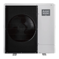
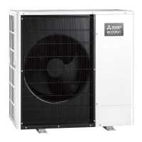
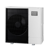
AIR TO WATER HEAT PUMP UNITS
OUTDOOR UNIT
[Model Name]
PUD-SWM60VAA
PUD-SWM80VAA
PUD-SWM100VAA
PUD-SWM120VAA
PUD-SWM80YAA
PUD-SWM100YAA
PUD-SWM120YAA
PUD-SHWM60VAA
PUD-SHWM80VAA
PUD-SHWM100VAA
PUD-SHWM120VAA
PUD-SHWM140VAA
PUD-SHWM80YAA
PUD-SHWM100YAA
PUD-SHWM120YAA
PUD-SHWM140YAA
[Service Ref.]
PUD-SWM60VAAR1
PUD-SWM80VAAR1
PUD-SWM100VAAR1
PUD-SWM120VAAR1
PUD-SWM80YAAR1
PUD-SWM100YAAR1
PUD-SWM120YAAR1
PUD-SHWM60VAAR1
PUD-SHWM80VAAR1
PUD-SHWM100VAAR1
PUD-SHWM120VAAR1
PUD-SHWM140VAAR1
PUD-SHWM80YAAR1
PUD-SHWM100YAAR1
PUD-SHWM120YAAR1
PUD-SHWM140YAAR1

Other manuals for Mitsubishi Electric PUD-SWM80VAA

Questions and Answers:

Mitsubishi Electric PUD-SWM80VAA Specifications

General IconGeneral
Cooling Capacity (kW)8.0
Heating Capacity (kW)9.0
RefrigerantR410A
Power Supply220-240 V, 50 Hz
Operating Temperature Range (Cooling)-5°C to 46°C

Summary

1. Reference Manual

2. Safety Precautions

2-1. General Safety Observance

General safety guidelines to follow before and during repair services.

2-2. R32 Refrigerant Handling Cautions

Specific safety warnings for handling R32 refrigerant.

3. Service Warnings and Cautions

Service Warnings and Cautions

Crucial warnings and guidelines for service personnel to ensure safety and correct procedures.

4. R32 Refrigerant Use Cautions

4-1. Cautions for R32 Refrigerant Unit Use

Detailed precautions when operating units with R32 refrigerant.

5. Service Tools

6. Reusing Existing Refrigerant Pipes

7. Outdoor Unit Installation Location

8. Minimum Installation Area

9. Specifications

10. Data

11. Outlines and Dimensions

12. Wiring Diagram

13. Wiring Specifications

14. Refrigerant System Diagram

14-1. Refrigerant Collecting (Pump Down)

Procedure for safely collecting refrigerant before unit relocation or disposal.

15. Troubleshooting

15-1. Troubleshooting Summary and Action Table

Overview of check codes, causes, and corrective actions for troubleshooting.

15-2. Troubleshooting Common Problems

15-2-1. Common Operational Issues and Countermeasures

Lists common operational issues and their corresponding countermeasures.

16. How to Check Parts

16-2. Checking High Pressure Sensor

17. Linear Expansion Valve Operation

18. Test Point Diagram

18-1. Outdoor Controller Circuit Board Diagram

Diagram showing test points and connections on the outdoor controller circuit board.

18-2. Outdoor Noise Filter Circuit Board Diagram

19. Switch, Connector, and Jumper Functions

19-1. Function of Switches

Details the functions and settings of various switches on the unit.

20. Special Functions

21. Outdoor Unit Inspection Display Functions

21-2. Abnormal Condition Display

Details error codes and blinking patterns indicating abnormal conditions.

22. Outdoor Unit Operation Monitor Function

22-1. Using A-Control Service Tool and LED Indicators

Guide to using the Service Tool and interpreting LED status lights and error codes.

23. SW2 Settings for Error Data Display

10. Monitoring Operation Data by Remote Controller

10-1-1. Request Code Detail Contents

Actuator Output State and Error Content (U9)

11. Disassembly Procedure

2. Removing Fan Motor and Electrical Parts Box

4. Disassembling Electrical Parts Box (V/Y-type Models)

6. Disassembling Electrical Parts Box (SHWM140V)

11. Removing Valve Coils, Pressure Switch, and Sensor

13. Removing the Compressor (MC)

Related product manuals