Do you have a question about the Mitsubishi Electric PUHY-P300 and is the answer not in the manual?
| Brand | Mitsubishi Electric |
|---|---|
| Model | PUHY-P300 |
| Category | Air Conditioner |
| Language | English |
Thoroughly read safety precautions, keep manual for future reference, and pass it to new users.
Use specific pipes, store them properly, and keep ends sealed to prevent contamination.
Use correct tools, handle with care, and follow specific procedures for R410A refrigerant.
Avoid gas leak areas, unusual environments, and areas prone to moisture or physical damage.
Ensures electrical safety through proper grounding, wiring, breaker usage, and avoiding water contact.
Covers safe unit handling, installation base checks, drain pipe installation, transportation, and packing disposal.
Essential steps before test run: unit power-on, electrical safety, pipe handling, panel installation, and air filter usage.
Check refrigerant type, symptoms, read safety precautions, prepare tools, verify pipes, and handle leaks safely.
Lists tools required for R410A, tools with restrictions, tools usable with R22/R407C, and tools that must not be used.
Details copper pipe materials, types, radial thickness, and specifications for R410A systems.
Covers proper storage of pipes indoors and preparation of flares and flanges with oil.
Outlines brazing procedures, emphasizing care to prevent foreign objects and use of non-oxidized solder.
Details pressurizing with nitrogen, judging airtightness, and notes on leak detectors for R410A.
Explains vacuum pump usage, vacuum degree standards, evacuation time, and special vacuum drying.
Covers refrigerant charging in liquid phase and remedies for refrigerant leaks.
Compares refrigerants and discusses notes on refrigerating machine oil for HFC systems.
Details system configurations and compatible indoor/outdoor unit combinations.
Specifies cable types, number of cores, cable size, and maximum transmission line distances.
Explains switch settings for various units and provides M-NET address settings.
Explains demand control operation, steps, and input/output signal configurations.
Provides sample system connection diagrams for MA, ME, and combined remote controllers.
Illustrates sample control wiring and cautions for MA remote controller systems.
Illustrates sample control wiring and cautions for ME remote controller systems.
Shows sample control wiring and cautions for systems with both MA and ME remote controllers.
Specifies refrigerant pipe diameters for outdoor units, branches, and indoor units.
Describes the control box, its internal components, and high-voltage warnings.
Details the outdoor unit control board, M-NET board, INV board, and fan board components.
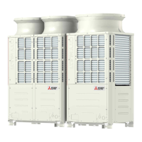
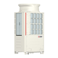
Provides a front view of outdoor units and identifies key components like fan, control box, and heat exchanger.
Illustrates the refrigerant circuit for different outdoor unit models (PUHY-P200 to P400, EP200 to EP250).
Details the refrigerant circuit for PUHY-P450YJM-A and PUHY-EP300YJM-A models.
Compares functions and specifications of MA and ME remote controllers.
Explains group settings and interlock settings using the ME remote controller.
Details setting up LOSSNAY interlocks with indoor units using the MA remote controller.
Describes how to use the built-in temperature sensor on the remote controller for accurate readings.
Provides the electrical wiring diagram for the outdoor unit, detailing connections and components.
Details the electrical wiring diagram for the transmission booster, showing connections and components.
Presents the refrigerant circuit diagram for various outdoor unit models.
Explains the principal parts and their functions in the outdoor unit, including compressor, sensors, and valves.
Details the functions and factory settings of dipswitches on the outdoor unit control board.
Explains functions of SW1, SW2, SW3, SW4, and SW5 dipswitches on the outdoor unit control board.
Details SW3 and SW5 dipswitch functions, including defrost timer, temperature settings, and model selection.
Explains functions of the INV board, controlled via a short-circuit connector for error detection.
Details the functions of indoor unit dipswitches SW1 and SW2.
Explains the functions of switches on the MA remote controller (PAR-20MAA) for settings like main/sub.
Details how to set the remote controller address using the rotary switch on the ME remote controller.
Explains the control method, startup sequence, initial control, and control at start-up of outdoor units.
Explains the functions of bypass solenoid valves (SV1a and SV9) for high and low pressure bypass.
Details compressor frequency control based on capacity, pressure limits, discharge temperature, and periodic control.
Explains the conditions for starting, stopping, and potential problems during defrost operation.
Describes refrigerant recovery during heating and cooling operations to prevent accumulation.
Explains how the outdoor unit fan speed is controlled by the inverter based on required capacity.
Details subcool coil control using LEV1, considering various sensor inputs and operating conditions.
Explains refrigerant flow control using LEV2 for heating and unusual operating conditions.
Describes the initial startup mode and its completion for various outdoor unit models.
Illustrates the mode determination flowchart for indoor units (cooling, heating, dry, fan).
Shows the operation flow chart for outdoor units in cooling and heating modes, including error handling.
Lists essential checks before starting a test run, including refrigerant leaks, wiring, and valve status.
Provides step-by-step instructions for performing a test run using the MA remote controller (PAR-21MAA).
Explains refrigerant characteristics and operating conditions crucial for adjusting refrigerant amount.
Details symptoms of over/undercharging and how to adjust refrigerant amount based on system conditions.
Explains procedures for adjusting refrigerant amount based on sensor readings and operational modes.
Lists symptoms that are considered normal during unit operation and their causes.
Presents standard operating data for cooling mode across various outdoor unit models.
Provides standard operating data for heating mode across various outdoor unit models.
Lists error codes, preliminary codes, definitions, and searched units for system troubleshooting.
Details the cause, check method, and remedy for serial communication errors (Error Code 0403).
Explains the cause, check method, and remedy for discharge temperature faults (Error Code 1102).
Details the cause, check method, and remedy for low pressure faults (Error Code 1301).
Explains the cause, check method, and remedy for high pressure faults (Error Code 1302).
Details the cause, check method, and remedy for refrigerant overcharge faults (Error Code 1500).
Explains the cause, check method, and remedy for drain sensor submergence (Error Code 2500).
Details the cause, check method, and remedy for drain pump faults (Error Code 2502).
Explains the cause, check method, and remedy for drain sensor faults (Error Code 2503).
Details the cause, check method, and remedy for water leakage faults (Error Code 2600).
Explains the cause, check method, and remedy for out-of-range outside air temperature faults (Error Code 3121).
Details the cause, check method, and remedy for open phase faults (Error Code 4102).
Explains the cause, check method, and remedy for transmission power supply faults (Error Code 4106).
Details the cause, check method, and remedy for indoor unit fan operation errors (Error Code 4109).
Explains the cause, check method, and remedy for power supply signal sync errors (Error Code 4115).
Details the cause, check method, and remedy for RPM or motor errors (Error Code 4116).
Explains causes and remedies for abnormal bus voltage drop and IPM/ground faults (Error Codes 4220, 4225).
Details causes and remedies for logic errors (Error Codes 4220, 4225).
Explains causes and remedies for heatsink overheat protection (4230) and related errors.
Details the cause, check method, and remedy for overload protection faults (Error Code 4240).
Explains causes and remedies for IPM errors (4250) and fan motor/board issues (4255).
Details causes and remedies for inverter output, grounding faults, and contactor issues for 4250/4255 errors.
Details causes and remedies for indoor/outdoor temperature sensor faults (Error Codes 5101-5104).
Explains causes and remedies for various sensor faults (TH2-TH7) and high-pressure sensor fault (5201).
Details causes and remedies for heatsink temperature sensor fault (5110) and high-pressure sensor fault (5201).
Explains causes and remedies for ACCT sensor faults (5301) and circuit faults.
Details causes and remedies for IPM/loose ACCT connector and faulty ACCT wiring errors (5301).
Explains causes and remedies for loose float switch connector (5701) and remote controller board faults (6201, 6202).
Details causes and remedies for address overlap (6600) and polarity setting errors (6601).
Explains causes and remedies for transmission processor hardware errors (Error Code 6602).
Details causes and remedies for transmission line bus busy errors (6603) and communication errors (6606).
Explains causes and remedies for no ACK errors (6607) in systems with one outdoor unit.
Details causes and remedies for no ACK errors (6607) in systems with multiple outdoor units.
Explains causes and remedies for no ACK errors (6607) in systems connected to system controllers (MELANS).
Provides detailed causes and remedies for no ACK errors (6607) when connected to system controllers.
Explains causes and remedies for total capacity errors (Error Code 7100).
Details causes and remedies for capacity code setting errors (Error Code 7101).
Explains causes and remedies for wrong number of connected units errors (Error Code 7102).
Details causes and remedies for address setting errors (Error Code 7105).
Explains causes and remedies for attribute setting errors (Error Code 7106).
Details causes and remedies for connection information signal transmission/reception errors (Error Code 7110).
Explains causes and remedies for remote controller sensor faults (Error Code 7111).
Details causes and remedies for function setting errors (Error Code 7113).
Explains causes and remedies for model setting errors (Error Code 7117).
Details causes and remedies for incompatible unit combination errors (Error Code 7130).
Provides methods for investigating transmission wave shape and noise on the M-NET line.
Details troubleshooting steps for the high-pressure sensor (63HS1) to check for failures.
Provides detailed analysis, comparison with gauge pressure, and sensor configuration for high-pressure sensor.
Details troubleshooting steps for the low-pressure sensor (63LS) to check for failures.
Explains how to check solenoid valve operation (SV1a, SV5b, SV5c, SV9) and their functions.
Provides troubleshooting steps for fan motor and electromagnetic contactor (52F) issues.
Details troubleshooting and remedies for inverter-related problems like board failure and loose connectors.
Provides simple checking procedures for IGBT module, rush current resistor, electromagnetic relay, and DC reactor.
Addresses inverter-related issues like electrolytic capacitor voltage, IPM damage, and wiring.
Explains how to read the LED monitor, interpret numerical values, and flag displays.
Details the initial LED display information shown before settings are completed.
Maps SW1 settings to corresponding LED display items (LD1-LD8) for outdoor unit operation status.
Explains how to interpret LED monitor data, including numerical values, flag displays, and initial settings.
Maps SW1 settings to display items (LD1-LD8) for outdoor unit operation status, including modes and errors.
Maps SW1 settings to display items for data before error conditions, showing temperatures and operation modes.
Maps SW1 settings to display items for data before error conditions, including pressures and temperatures.
Maps SW1 settings to display items for data before error conditions, covering compressor and fan operation.
Maps SW1 settings to display items for indoor unit data, including address, capacity, and operation mode.
Maps SW1 settings to display items for indoor unit data, including suction and liquid pipe temperatures.
Maps SW1 settings to display items for indoor unit gas pipe temperatures.
Maps SW1 settings to display items for indoor unit liquid pipe temperatures.
Maps SW1 settings to display items for indoor unit operation modes like Stop, Ventilation, Cooling, and Heating.
Maps SW1 settings to display items for indoor unit operation modes, including control statuses.
Maps SW1 settings to display items for indoor unit control statuses like communication and capacity.
Maps SW1 settings to display items for indoor unit miscellaneous data, including compressor operation time.
Maps SW1 settings to display items for indoor unit miscellaneous data, like compressor operation time and filter status.
Maps SW1 settings to display items for indoor unit filter status and operation modes.
Maps SW1 settings to display items for indoor unit operation modes, including Stop, Ventilation, Cooling, and Heating.
Maps SW1 settings to display items for indoor unit gas pipe temperatures.
Maps SW1 settings to display items for indoor unit liquid pipe temperatures.
Maps SW1 settings to display items for indoor unit operation modes, including Stop, Ventilation, Cooling, and Heating.
Maps SW1 settings to display items for indoor unit filter status and maintenance intervals.
Maps SW1 settings to display items for indoor unit filter status.


 Loading...