Do you have a question about the Mitsubishi Electric PUHY-P200 and is the answer not in the manual?
| Model | PUHY-P200 |
|---|---|
| Cooling Capacity | 22.4 kW |
| Heating Capacity | 25.0 kW |
| Refrigerant | R410A |
| Power Supply | 380-415V, 3Ph, 50Hz |
| Operating Temperature (Cooling) | -5°C to 46°C |
| Series | City Multi |
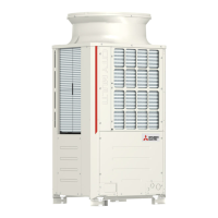
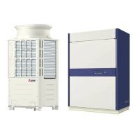
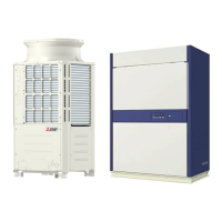
| Type | Outdoor Unit |
| Dimensions (Indoor Unit) | N/A (Depends on indoor unit model) |
| Weight (Indoor Unit) | N/A (Depends on indoor unit model) |
Essential safety instructions for installation, operation, and handling to prevent injury and damage.
Covers refrigerant checks, tools, piping, brazing, testing, vacuuming, charging, and oil notes for servicing.
Details compatible indoor units, system configurations, and high COP combinations.
Specifies cable types, lengths, wiring practices, and control wiring requirements.
Covers switch settings, M-NET address settings, and demand control configurations.
Provides system connection examples and restrictions on pipe length and diameter.
Details front view components, control box, circuit board, and refrigerant circuit diagrams for outdoor units.
Explains the components within the control box and the details of the outdoor unit circuit board.
Compares MA/ME controllers, explains group/interlock settings, and address management.
Procedures for group settings, interlock setup, address search, and deletion via remote controllers.
Detailed electrical wiring diagram for the outdoor unit, covering various models and components.
Electrical wiring diagram specific to the transmission booster.
Illustrates the refrigerant circuit diagrams for different outdoor unit models.
Details the principal parts of the outdoor unit and their functions, including sensors and valves.
Explains the functions and factory settings of dipswitches on the control board and other units.
Outlines control methods for outdoor units, including startup sequence, bypass, frequency, defrost, and recovery.
Provides flowcharts for indoor and outdoor unit operation modes (cooling, heating, dry).
Lists essential checks before test run and guides the test run procedure using the remote controller.
Covers refrigerant characteristics, adjustment procedures, and normal operating symptoms.
Provides standard operating data for cooling and heating operations of various unit combinations.
Lists error codes, definitions, and detailed responses for troubleshooting.
Guides on investigating transmission issues and troubleshooting major unit components.
Procedures for identifying refrigerant leaks and instructions for compressor replacement.
Instructions for troubleshooting errors using the outdoor unit LED display.
Explains how to read the LED display, including numerical values and flag displays.
Details LED displays during initial settings, time data storage, and SW1 item descriptions.