Do you have a question about the Mitsubishi Electric PUHY-P250YMF-C and is the answer not in the manual?
| Brand | Mitsubishi Electric |
|---|---|
| Model | PUHY-P250YMF-C |
| Category | Air Conditioner |
| Language | English |
Guidelines for storing refrigerant piping materials indoors, ensuring cleanliness and sealing ends.
Instructions for coating flare and flange connections with ester oil, ether oil, or alkylbenzene.
Comparison of tools for R407C and R22, highlighting dedicated tools and handling notes.
Careful brazing procedures to prevent foreign matter entry, emphasizing non-oxide brazing.
Procedure for pressurizing with nitrogen and checking for leaks, noting R22 detectors are unsuitable.
Requirements for vacuum pumps, gauges, and evacuation time to achieve the standard vacuum degree.
Ensuring R407C is in liquid state during charging due to its non-azeotropic nature.
Guidelines for replacing the dryer with a CITY MULTI Series Y model for R407C.
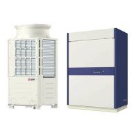
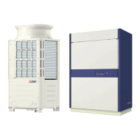
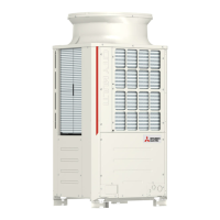
Illustrations showing the layout of major components within outdoor units for different model series.
Detailed refrigerant circuit diagrams for various PU(H)Y, PUY, and PURY models.
Wiring diagrams for PU(H)Y-(P)200·250YMF-C and PURY-(P)200·250YMF-C models.
Tables detailing standard operating data for cooling and heating operations for various models.
Explanation of DIP switch settings for outdoor and indoor units for various functions.
Check points before test run, including power source, piping, and crankcase heater status.
Step-by-step procedure for conducting a test run and verifying operations.
Explanation of switch functions on the remote controller for unit registration and group settings.
Display of unit/controller types during registration and connection information retrieval.
Details on initial processing, starting control, bypass/capacity control, and frequency control.
Operation control for SVA, SVB, SVC, SVM, and LEV based on different modes.
Flowcharts illustrating the operation logic for outdoor units, BC controllers, and indoor units.
Troubleshooting procedures for pressure sensors, including judging failure and checking configuration.
Troubleshooting based on check codes, covering mechanical, communication, and system errors.
Guide on reading service LEDs on the control circuit board for numerical and graphic display.
Procedures for locating refrigerant leaks in piping, indoor units, and outdoor units for cooling/heating.
Steps to check and calibrate refrigerant composition (αOC) for PURY-P200·250YMF-C models.