Do you have a question about the Mitsubishi Electric PUHY-P250YNW-A and is the answer not in the manual?
| Brand | Mitsubishi Electric |
|---|---|
| Model | PUHY-P250YNW-A |
| Category | Air Conditioner |
| Language | English |
General safety guidelines for operating and installing the unit.
Steps and precautions for installing the unit.
Pre-service checks and preparation steps for piping.
List of necessary tools for servicing the unit.
Details on copper pipe materials and radial thickness.
Procedure and precautions for performing an air tightness test.
Steps and standards for vacuum drying the refrigerant circuit.
Procedure and reasons for refrigerant charging.
Safety precautions and guidelines for wiring work.
Configuration options and limitations for different system setups.
Specifications for control wiring cables and their maximum lengths.
Overview of demand control functionality and settings.
Limits and guidelines for refrigerant pipe lengths in different systems.
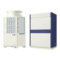
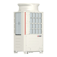
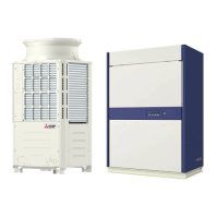
Identification of external parts of the outdoor unit.
Diagrams and explanation of the outdoor unit's refrigerant circuits.
Identification of internal components within the indoor unit.
Schematic diagrams illustrating the refrigerant circuits.
Detailed explanation of the functions of major outdoor unit components.
Arrangement and components within the outdoor unit control box.
Arrangement and components within the indoor unit control box.
Detailed layout and connections of the outdoor unit control board.
Detailed layout and components of the outdoor unit inverter board.
Schematic diagrams illustrating the electrical connections of the system.
Configuration of dipswitch functions and factory settings.
Overview of outdoor unit control logic and operation modes.
Procedures for activating and ending emergency operation mode.
Control logic and functions for indoor units.
Important checks and precautions before performing a test run.
Methods for evaluating and adjusting refrigerant charge.
Lists of error codes and their preliminary definitions.
Detailed definitions and solutions for error codes 0-999.
Detailed definitions and solutions for error codes 4000-4999.
Detailed definitions and solutions for error codes 5000-5999.
Common issues and troubleshooting for MA remote controllers.
Troubleshooting common problems related to refrigerant control.
Configuration and troubleshooting for pressure sensor circuits.
Diagnostic steps and solutions for solenoid valve issues.
Identification and resolution of outdoor unit fan problems.
Diagnosing and resolving issues with Linear Expansion Valves (LEV).
Solutions for common problems related to the inverter system.
Procedures for identifying and addressing refrigerant leaks.
Step-by-step instructions for replacing various unit parts.
Recommended schedule for unit maintenance and inspection.
Overview of USB port functions for service operations.
Procedures for collecting and storing operational data via USB.
Instructions for rewriting unit software using a USB drive.
Interpreting maintenance LED displays and troubleshooting USB issues.
Explanation of how to interpret LED displays for status monitoring.
Information displayed on LEDs during initial unit startup.
Comprehensive table detailing LED status indicators and their meanings.