EasyManua.ls Logo

Mitsubishi Electric PUHY-P200YMF-C User Manual

Mitsubishi Electric PUHY-P200YMF-C
166 pages
To Next Page IconTo Next Page
Page #1 background imageLoading...
Page #1 background image
AIR CONDITIONERS CITY MULTI
Models PUHY-200YMF-C, 250YMF-C
PUHY-P200YMF-C, P250YMF-C
PUY-200YMF-C, 250YMF-C
PUY-P200YMF-C, P250YMF-C
PURY-200YMF-C, 250YMF-C
PURY-P200YMF-C, P250YMF-C
CMB-P104, P105, P106, P108, P1010, P1013, P1016V-E
Service Handbook

Table of Contents

Question and Answer IconNeed help?

Do you have a question about the Mitsubishi Electric PUHY-P200YMF-C and is the answer not in the manual?

Mitsubishi Electric PUHY-P200YMF-C Specifications

General IconGeneral
TypeHeat Pump
Cooling Capacity (kW)22.4
Heating Capacity (kW)25.0
RefrigerantR410A
Power Source380-415V, 50Hz
Operating Temperature (Cooling)-5°C to 46°C

Summary

AIR CONDITIONERS CITY MULTI

Service Handbook

Provides detailed service information for the City Multi air conditioning system.

Safety Precautions

General Safety Information and Symbols

Covers installation safety, symbols for warnings, and caution notes.

1 PRECAUTIONS FOR DEVICES THAT USE R407C REFRIGERANT

Refrigerant Handling and Piping Precautions

Essential guidelines for safe handling and piping of R407C refrigerant.

1.1 Storage of Piping Material

Storage Location and Pipe Sealing

Proper storage methods for piping to prevent contamination and moisture.

1.2 Piping Machining

Machining and Oil Application Procedures

Guidelines for machining pipes and applying appropriate oil for connections.

1.3 Necessary Apparatus and Materials

Apparatus Comparison and Handling Notes

Comparison of tools for R407C vs R22 and notes on their handling.

1.4 Brazing

Brazing Methods and Precautions

Special care required during brazing to prevent foreign matter intrusion.

1.5 Airtightness Test

Airtightness Testing Procedures and Tools

Methods for testing system airtightness and required tools.

1.6 Vacuuming

Vacuuming Procedures and Requirements

Guidelines for vacuum pump usage and achieving the standard vacuum degree.

1.7 Charging of Refrigerant

Refrigerant Charging Method and Cylinder Identification

Procedure for charging refrigerant in liquid state and cylinder identification.

1.8 Dryer

Dryer Replacement Guidelines

Instructions for replacing the dryer and timing of replacement.

2 COMPONENT OF EQUIPMENT

Appearance of Components Overview

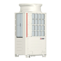
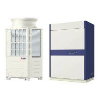
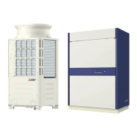
Illustrations showing the components of outdoor units.

2.2 Refrigerant Circuit Diagram and Thermal Sensor

PUHY-200YMF-C, 250YMF-C Circuit Diagram

Refrigerant circuit diagram for PUHY-200/250YMF-C models.

3 Electrical Wiring Diagram

PU(H)Y-(P)200·250YMF-C Wiring Diagram

Detailed electrical wiring diagram for PU(H)Y-(P)200/250YMF-C units.

4 Standard Operation Data

Cooling Operation Data

Standard operation data for cooling mode across different models.

4 Standard Operation Data

Heating Operation Data

Standard operation data for heating mode across different models.

5 CONTROL

Control of Outdoor Unit

Details on outdoor unit initial processing, start control, and bypass operations.

5 CONTROL

Outdoor Unit Control Details

Information on initial processing, start control, and bypass/capacity control.

5 CONTROL

Frequency Control

Explanation of frequency control starting, pressure limits, and discharge temperature.

5 CONTROL

Oil Return, Subcool Coil, and Defrost Controls

Details on oil return, subcool coil, and defrost operation controls.

5 CONTROL

Refrigerant Recovery and Fan/Heat Exchanger Control

Procedures for refrigerant recovery and control of fan/heat exchanger.

5 CONTROL

BC Controller Operations

Control logic for BC controller valves (SVA, SVB, SVC, SVM) and LEV.

5 CONTROL

Operation Flow Chart: Outdoor Unit

Flowchart detailing the outdoor unit's operation logic.

5 CONTROL

Operation Flow Chart: BC Controller (PURY)

Flowchart illustrating the BC controller's operation for PURY models.

5 CONTROL

Operation Flow Chart: Indoor Unit

Flowchart detailing the indoor unit's operation logic.

5 CONTROL

Cooling Operation Flow

Step-by-step flowchart for cooling operation.

5 CONTROL

Heating Operation Flow

Step-by-step flowchart for heating operation.

5 CONTROL

Dry Operation Flow

Step-by-step flowchart for dry operation mode.

[4] List of Major Component Functions

Outdoor Unit Component Functions

Description of major outdoor unit components and their functions.

[4] List of Major Component Functions

BC Controller Component Functions

Description of major BC controller components and their functions.

6 REFRIGERANT AMOUNT ADJUSTMENT

Refrigerant Amount and Operating Characteristics

Relationship between refrigerant amount and system operation characteristics.

6 REFRIGERANT AMOUNT ADJUSTMENT

Adjusting and Judging Refrigerant Volume

Symptoms and methods for adjusting and judging refrigerant volume.

6 REFRIGERANT AMOUNT ADJUSTMENT

Refrigerant Volume Adjustment Operation (PU(H)Y-(P)200·250YMF-C)

Detailed operation for adjusting refrigerant volume on specific models.

6 REFRIGERANT AMOUNT ADJUSTMENT

Additional Refrigerant Charge Volume Calculation

Formula and table for calculating additional refrigerant charge.

6 REFRIGERANT AMOUNT ADJUSTMENT

Refrigerant Volume Adjustment Mode Operation Procedure

Step-by-step procedure for operating the refrigerant volume adjustment mode.

6 REFRIGERANT AMOUNT ADJUSTMENT

Refrigerant Volume Adjustment Flowchart (PUHY-P200, 250YMF-C)

Flowchart for adjusting refrigerant volume on PUHY-P200/250YMF-C models.

6 REFRIGERANT AMOUNT ADJUSTMENT

Refrigerant Volume Adjustment Mode Operations (PURY-(P)200·250YMF-C)

Operation details for refrigerant volume adjustment on PURY-(P)200/250YMF-C.

6 REFRIGERANT AMOUNT ADJUSTMENT

Refrigerant Volume Adjustment Flowchart (PURY-200, 250YMF-C)

Flowchart for adjusting refrigerant volume on PURY-200/250YMF-C models.

7 TROUBLESHOOTING

Principal Parts: Pressure Sensor Troubleshooting

Troubleshooting steps for pressure sensors, including failure judging.

7 TROUBLESHOOTING

Pressure Sensor Configuration and Solenoid Valve Checks

Checking pressure sensor configuration and solenoid valve operations.

7 TROUBLESHOOTING

Solenoid Valve (SV1~6) Troubleshooting (PURY-(P)200·250YMF-C)

Troubleshooting specific solenoid valves for PURY models.

7 TROUBLESHOOTING

Solenoid Valve Troubleshooting Details

Detailed troubleshooting steps for solenoid valves.

7 TROUBLESHOOTING

Outdoor LEV (SLEV) Coil Removal Procedure

Procedure for removing the coil from the outdoor LEV.

7 TROUBLESHOOTING

LEV Valve Closing and Opening Operations

Explanation of LEV valve operation and checking methods.

Troubleshooting and Likely Failure Mode

Microcomputer Driver Circuit Failure

Troubleshooting steps for microcomputer driver circuit failures.

Troubleshooting and Likely Failure Mode

Check Valves Block (PURY-(P)200·250YMF-C)

Details on check valves block for PURY models and screw key sizes.

Troubleshooting and Likely Failure Mode

Intelligent Power Module (IPM) and Diode Stack Troubleshooting

Troubleshooting methods for IPM and diode stack components.

Trouble and Remedy of Remote Controller

Symptom 1: No Electronic Sound

Troubleshooting steps when remote controller has no response.

Transmission Power Circuit (30 V) Check Procedure

Check Procedure Details

Detailed steps for checking the 30V transmission power circuit.

Investigation of Transmission Wave Shape/Noise

Symptom Caused by Noise

Identifying symptoms caused by noise on the transmission line.

Treatment of Inverter and Compressor Troubles

Troubleshooting Inverter Output Voltage

Steps to troubleshoot inverter output voltage issues.

Treatment of Inverter and Compressor Troubles

Treatment of Fan Motor Related Troubles

Troubleshooting and remedies for fan motor issues.

Treatment of Inverter and Compressor Troubles

Troubleshooting at Breaker Tripping

Procedures for troubleshooting breaker tripping issues.

Treatment of Inverter and Compressor Troubles

Individual Parts Failure Judgment Methods

Methods for judging the failure of individual internal parts.

Troubleshooting the Major Components of the BC Controller

Pressure Sensor Troubleshooting Flow

Flowchart for troubleshooting BC controller pressure sensors.

Troubleshooting the Major Components of the BC Controller

Pressure Sensor Notes and Replacement Precautions

Important notes and precautions for pressure sensor replacement.

Troubleshooting the Major Components of the BC Controller

Temperature Sensor Troubleshooting Flow

Flowchart for troubleshooting BC controller temperature sensors.

Troubleshooting the Major Components of the BC Controller

Temperature Sensor Notes and Resistance Graphs

Notes and resistance graphs for temperature sensors.

Troubleshooting the Major Components of the BC Controller

LEV, Solenoid Valve Troubleshooting Flow

Troubleshooting flowchart for LEV and solenoid valves.

Troubleshooting the Major Components of the BC Controller

LEV Operation Characteristics and Troubleshooting

Characteristics of LEV operation and related troubleshooting.

Troubleshooting the Major Components of the BC Controller

LEV Troubleshooting Methods

Methods for checking LEV full open/closed conditions.

Troubleshooting the Major Components of the BC Controller

Solenoid Valve Troubleshooting

Troubleshooting steps for solenoid valves.

Troubleshooting the Major Components of the BC Controller

Solenoid Valve Operations and BC Controller Transformer

Coordination of solenoid valves and BC controller transformer checks.

[2] BC Controller Disassembly Procedure

Service Panel Disassembly

Procedure for disassembling the service panel of the BC controller.

[2] BC Controller Disassembly Procedure

Control Box Disassembly

Procedure for disassembling the control box.

[2] BC Controller Disassembly Procedure

Thermistor Disassembly and Replacement

Procedure for disassembling and replacing thermistors.

[2] BC Controller Disassembly Procedure

Pressure Sensor Disassembly and Installation

Procedure for disassembling and installing pressure sensors.

[2] BC Controller Disassembly Procedure

LEV Disassembly Procedures

Procedures for disassembling LEV components.

[2] BC Controller Disassembly Procedure

Solenoid Valve Coil Disassembly

Procedure for disassembling solenoid valve coils.

Check Code List

Serial Transmission Abnormality (0403)

Troubleshooting for serial transmission errors.

Check Code List

Discharge Temperature Abnormality (1102)

Troubleshooting for discharge temperature abnormalities.

Check Code List

Low Pressure Saturation Temperature Sensor Abnormality (1111)

Troubleshooting for low pressure saturation temperature sensor errors.

Check Code List

Pressure Abnormalities (1301, 1302, 1368, 1370)

Troubleshooting for various pressure abnormalities.

Check Code List

Refrigerant Amount and Leakage Abnormalities (1500, 1501, 1505, 2500)

Troubleshooting for refrigerant amount and leakage errors.

Check Code List

Drain Pump/Sensor and Float Switch Errors (2502, 2503)

Troubleshooting for drain pump, sensor, and float switch errors.

Check Code List

Phase and Power Supply Abnormalities (4103, 4115)

Troubleshooting for phase and power supply abnormalities.

Check Code List

Fan Speed and VDC Sensor/Circuit Abnormalities (4116, 4200)

Troubleshooting for fan speed and VDC sensor/circuit errors.

Check Code List

Bus Voltage and Radiator Panel Overheat Abnormalities (4220, 4230)

Troubleshooting for bus voltage and radiator panel overheat errors.

Check Code List

Overload Protection and IPM Alarm Output Abnormalities (4240, 4250)

Troubleshooting for overload and IPM alarm output errors.

Check Code List

Cooling Fan Abnormality (4260)

Troubleshooting for cooling fan abnormalities.

Check Code List

Thermal Sensor Abnormalities (5101-5112)

Troubleshooting for various thermal sensor abnormalities.

Check Code List

Pressure Sensor Abnormalities (5201, 5203)

Troubleshooting for pressure sensor abnormalities.

Check Code List

IAC Sensor/Circuit and Different Indoor Model Abnormalities (5301, 7130)

Troubleshooting for IAC sensor/circuit and model mismatch errors.

Check Code List

Communication/System Errors: Multiple Address Error (6600)

Troubleshooting communication errors related to multiple addresses.

Check Code List

Communication/System Errors: Transmission Processor Hardware Error (6602)

Troubleshooting transmission processor hardware errors.

Check Code List

Communication/System Errors: Transmission Processor Error (6606)

Troubleshooting communication errors related to transmission processor.

Check Code List

Communication/System Errors: No ACK Error (6607) - Single Refrigerant System

Troubleshooting No ACK errors in single refrigerant systems.

Check Code List

Communication/System Errors: No ACK Error (6607) - Plural Refrigerant Systems

Troubleshooting No ACK errors in plural refrigerant systems.

Check Code List

Communication/System Errors: No ACK Error (6607) - MELANS System

Troubleshooting No ACK errors in MELANS systems.

Check Code List

System Errors: Total Capacity Error (7100)

Troubleshooting errors related to total system capacity.

Check Code List

Check Code List

System Errors: Remote Control Sensor and Different Indoor Model Errors (7111, 7130)

Troubleshooting remote sensor and model mismatch errors.

[4] LED Monitor Display

How to Read LED for Service Monitor

Guide to interpreting LED displays on the service monitor.

[4] LED Monitor Display

SW1 Item Display (PU(H)Y-(P)200·250YMF-C) - Relay Output and Error Details

LED display data for SW1 items: relay output and error details.

[4] LED Monitor Display

SW1 Item Display (PU(H)Y-(P)200·250YMF-C) - Preliminary and Sensor Data

LED display data for SW1 items: preliminary and sensor readings.

[4] LED Monitor Display

SW1 Item Display (PU(H)Y-(P)200·250YMF-C) - Temperature and Other Data

LED display data for SW1 items: temperature and other operational data.

[4] LED Monitor Display

SW1 Item Display (PU(H)Y-(P)200·250YMF-C) - Temperature and Other Data Continued

Continued LED display data for SW1 items: temperature and other data.

[4] LED Monitor Display

SW1 Item Display (PU(H)Y-(P)200·250YMF-C) - Temperature Data

LED display data for SW1 items: temperature readings.

[4] LED Monitor Display

SW1 Item Display (PU(H)Y-(P)200·250YMF-C) - Gas Pipe Temperature and SH Data

LED display data for SW1 items: gas pipe temperature and SH.

[4] LED Monitor Display

SW1 Item Display (PU(H)Y-(P)200·250YMF-C) - SC and LEV Opening Pulse Data

LED display data for SW1 items: SC and LEV opening pulse.

[4] LED Monitor Display

SW1 Item Display (PU(H)Y-(P)200·250YMF-C) - Operation Mode and Filter Data

LED display data for SW1 items: operation mode and filter status.

8 PREPARATION, REPAIRS AND REFRIGERANT REFILLING WHEN REPAIRING LEAKS

Location of Leaks: Extension Piping or Indoor Units (Cooling)

Procedure to locate leaks in extension piping or indoor units during cooling.

8 PREPARATION, REPAIRS AND REFRIGERANT REFILLING WHEN REPAIRING LEAKS

Location of Leaks: Outdoor Unit (Cooling Mode)

Procedure to locate leaks in the outdoor unit during cooling mode.

8 PREPARATION, REPAIRS AND REFRIGERANT REFILLING WHEN REPAIRING LEAKS

Location of Leaks: Extension Piping or Indoor Units (Heating Mode)

Procedure to locate leaks in extension piping or indoor units during heating.

8 PREPARATION, REPAIRS AND REFRIGERANT REFILLING WHEN REPAIRING LEAKS

Location of Leaks: Outdoor Unit (When Heating)

Procedure to locate leaks in the outdoor unit during heating.

9 CHECK THE COMPOSITION OF THE REFRIGERANT (PURY-P200·250YMF-C only)

Refrigerant Composition Check Flowchart

Flowchart for checking the refrigerant composition.

9 CHECK THE COMPOSITION OF THE REFRIGERANT (PURY-P200·250YMF-C only)

Notes on Refrigerant Composition Check and Calibration

Notes and calibration steps for refrigerant composition check.

Related product manuals