EasyManua.ls Logo

Mitsubishi Electric PUHZ-HRP125YHA User Manual

Mitsubishi Electric PUHZ-HRP125YHA
119 pages
To Next Page IconTo Next Page
Page #1 background imageLoading...
Page #1 background image
SERVICE MANUAL
No.OCH425
REVISED EDITION-D
SPLIT-TYPE, HEAT PUMP AIR CONDITIONERS
R410A
October 2011
PUHZ-HRP71VHA
PUHZ-HRP100VHA
PUHZ-HRP100YHA
PUHZ-HRP125YHA
Note:
• This manual describes only
service data of the outdoor
units.
• RoHS compliant products
have <G> mark on the spec
name plate.
PARTS CATALOG (OCB425)
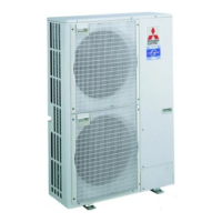
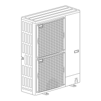
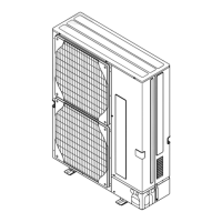
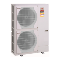
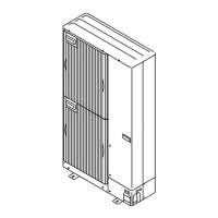
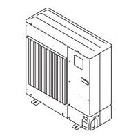
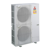
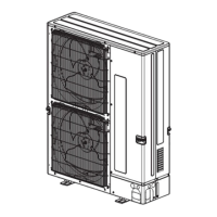
Outdoor unit
[Model names]
PUHZ-HRP71VHA
PUHZ-HRP100VHA
PUHZ-HRP100YHA
PUHZ-HRP125YHA
PUHZ-HRP71VHA2
PUHZ-HRP100VHA2
PUHZ-HRP100YHA2
PUHZ-HRP125YHA2
[Service Ref.]
PUHZ-HRP71VHA
PUHZ-HRP100VHA
PUHZ-HRP100YHA
PUHZ-HRP125YHA
PUHZ-HRP71VHA2
PUHZ-HRP71VHA2R1
PUHZ-HRP100VHA2
PUHZ-HRP100VHA2R1
PUHZ-HRP100VHA2R2
PUHZ-HRP100YHA2
PUHZ-HRP100YHA2R1
PUHZ-HRP125YHA2
PUHZ-HRP125YHA2R1
CONTENTS
1. TECHNICAL CHANGES ·······························2
2. REFERENCE MANUAL ································2
3. SAFETY PRECAUTION ·······························3
4. FEATURES ···················································7
5. SPECIFICATIONS ········································8
6. DATA ·····························································9
7. OUTLINES AND DIMENSIONS··················12
8. WIRING DIAGRAM ·····································14
9. WIRING SPECIFICATIONS ························20
10. REFRIGERANT SYSTEM DIAGRAM ········25
11. TROUBLESHOOTING ································27
12. FUNCTION SETTING ·································85
13.
MONITORING THE OPERATION DATA BY THE REMOTE CONTROLLER
····92
14. EASY MAINTENANCE FUNCTION ·········102
15. DISASSEMBLY PROCEDURE ·················107
Revision:
"11-10 FUNCTION OF
SWITCHES, CONNECTORS
AND JUMPERS" has been
modified in REVISED
EDITION-D. (See page 80)
Some descriptions have been
modified.
• Please void OCH425
REVISED EDITION-C.

Table of Contents

Other manuals for Mitsubishi Electric PUHZ-HRP125YHA

Questions and Answers:

Mitsubishi Electric PUHZ-HRP125YHA Specifications

General IconGeneral
ModelPUHZ-HRP125YHA
TypeHeat Pump
Cooling Capacity12.5 kW
Heating Capacity14.0 kW
RefrigerantR410A
Operating Range Cooling-10°C to 46°C
Operating Range Heating-20°C to 24°C

Summary

TECHNICAL CHANGES

REFERENCE MANUAL

INDOOR UNIT SERVICE MANUAL

Lists service manuals for various indoor units and their corresponding service ref/manual numbers.

TECHNICAL DATABOOK

Identifies the technical databook manual number.

SAFETY PRECAUTION

ALWAYS OBSERVE FOR SAFETY

General safety rules to follow before and during repair service.

CAUTIONS RELATED TO NEW REFRIGERANT

Specific precautions for using R410A refrigerant and associated tools.

Cautions for service

General cautions to follow when performing service related to refrigerant.

Additional refrigerant charge

Procedures and cautions for charging refrigerant from a cylinder.

Service tools

Lists service tools required for R410A refrigerant work with specifications.

Refrigerant leakage detection function

Explains the leakage detection feature and initial learning requirements.

PRECAUTIONS WHEN REUSING EXISTING R22 REFRIGERANT PIPES

Flowchart and guidelines for reusing R22 refrigerant pipes with R410A units.

Cautions for refrigerant piping work

Details on R410A refrigerant piping thickness, flare dimensions, and tool compatibility.

FEATURES

HIGH HEATING CAPACITY

Highlights the flash injection circuit for enhanced heating capacity.

HIGH SPEED HEATING START UP

Describes improvements in heating start-up time and airflow temperature.

WIDE HEATING RANGE

Mentions the expanded heating range down to -25°C.

CHARGELESS SYSTEM

Explains the pre-charged refrigerant system for simplified installation.

REFRIGERANT LEAKAGE DETECTION FUNCTION

Notes the leakage detection capability of specific models.

SPECIFICATIONS

DATA

REFILLING REFRIGERANT CHARGE (R410A : kg)

Table showing refrigerant charge amounts based on piping length.

COMPRESSOR TECHNICAL DATA

Provides winding resistance data for different compressor models.

NOISE CRITERION CURVES

Presents noise criterion curves for different models under cooling and heating modes.

STANDARD OPERATION DATA

Table detailing standard operation data for representative indoor/outdoor unit matching.

OUTLINES AND DIMENSIONS

FREE SPACE (Around the unit)

Specifies required clearance around the unit for installation and service.

SERVICE SPACE

Details required space for service access.

FOUNDATION BOLTS

Information on foundation bolt requirements and placement.

PIPING-WIRING DIRECTIONS

Explains piping and wiring connection options from different directions.

Piping Knockout Hole Details

Diagram showing dimensions and locations of knockout holes for piping and wiring.

WIRING DIAGRAM

PUHZ-HRP71VHA PUHZ-HRP100VHA

Wiring diagram for specific outdoor unit models.

M-NET ADAPTER

Lists components and connections for the M-NET adapter.

1. MODEL SELECT

Explains the function of model select switches SW5 and SW6.

PUHZ-HRP100YHA PUHZ-HRP125YHA

Wiring diagram for different outdoor unit models.

PUHZ-HRP71VHA2 PUHZ-HRP100VHA2

Wiring diagram for specific outdoor unit models.

PUHZ-HRP100YHA2 PUHZ-HRP125YHA2

Wiring diagram for different outdoor unit models.

PUHZ-HRP71VHA2R1 PUHZ-HRP100VHA2R1 PUHZ-HRP100VHA2R2

Wiring diagram for specific outdoor unit models.

PUHZ-HRP100YHA2R1 PUHZ-HRP125YHA2R1

Wiring diagram for different outdoor unit models.

WIRING SPECIFICATIONS

FIELD ELECTRICAL WIRING (power wiring specifications)

Details power wiring specifications for different outdoor unit models and wiring sizes.

SEPARATE INDOOR UNIT/ OUTDOOR UNIT POWER SUPPLIES

Explains connection patterns for separate indoor/outdoor unit power supplies.

INDOOR – OUTDOOR CONNECTING CABLE

Specifies requirements for indoor-outdoor connecting cables, including length and wire size.

M-NET WIRING METHOD

Provides notes and examples for M-NET wiring, including grounding methods.

M-NET address setting

Instructions for setting M-NET addresses using rotary switches.

Refrigerant address setting

Guidelines for setting refrigerant addresses using DIP switches.

Regulations in address settings

Rules for setting M-NET and refrigerant addresses in multi-unit systems.

REFRIGERANT SYSTEM DIAGRAM

Refrigerant recovering (pump down)

Unit replacement operation (except for PUHZ-HRP·HA2R1)

Procedure for replacing R22 pipes with R410A units, including operation steps.

Start and finish of test run

Instructions for performing and completing a test run using DIP switches.

TROUBLESHOOTING

TROUBLESHOOTING

Summary of actions based on error code display and reoccurrence status.

CHECK POINT UNDER TEST RUN

Points to check before performing a test run, including electrical checks.

The below symptoms are under test run mode.

Table describing symptoms, causes, and LED displays during test run.

Test run [for wireless remote controller]

Procedure for conducting a test run using a wireless remote controller.

HOW TO PROCEED “SELF-DIAGNOSIS”

General procedure for self-diagnosis when a problem occurs.

When a Problem Occurs During Operation

How errors are displayed and cleared during operation.

Self-Diagnosis During Maintenance or Service

Steps to access and check error code history during maintenance.

Remote Controller Diagnosis

Steps to diagnose issues with the remote controller itself.

Malfunction-diagnosis method by wireless remote controller

Procedures for malfunction diagnosis using a wireless remote controller.

Errors detected by indoor unit

Table listing errors detected by the indoor unit with check codes and symptoms.

Errors detected by unit other than indoor unit (outdoor unit, etc.)

Table listing errors detected by outdoor units with check codes and symptoms.

SELF-DIAGNOSIS ACTION TABLE

Table detailing actions for abnormalities detected when power is turned on.

Abnormalities detected when unit is operating

Lists error codes and conditions detected during unit operation.

Abnormalities detected while unit is operating

Continues the list of abnormalities detected during unit operation.

Abnormalities detected while unit is operating

Continues the list of abnormalities detected during unit operation.

Abnormalities detected while unit is operating

Continues the list of abnormalities detected during unit operation.

Abnormalities detected while unit is operating

Continues the list of abnormalities detected during unit operation.

Abnormalities detected while unit is operating

Continues the list of abnormalities detected during unit operation.

Abnormalities detected while unit is operating

Continues the list of abnormalities detected during unit operation.

M-NET communication error

Details M-NET communication errors and their troubleshooting steps.

M-NET communication error (continued)

Continues details on M-NET communication errors and troubleshooting.

M-NET communication error (continued)

Continues details on M-NET communication errors and troubleshooting.

TROUBLESHOOTING BY INFERIOR PHENOMENA

Troubleshooting steps for common inferior phenomena observed during operation.

TROUBLESHOOTING BY INFERIOR PHENOMENA (continued)

Continues troubleshooting steps for inferior phenomena.

Symptoms: “PLEASE WAIT” is kept being displayed on the remote controller.

Diagnosis flow for "PLEASE WAIT" display issues on the remote controller.

Symptoms: Nothing is displayed on the remote controller

Diagnosis flow for issues where nothing is displayed on the remote controller.

Symptoms: Nothing is displayed on the remote controller (continued)

Continues the diagnosis flow for remote controller display issues.

Symptoms: Nothing is displayed on the remote controller (continued)

Continues the diagnosis flow for remote controller display issues.

Phone Calls From Customers

Categorizes customer inquiries and provides response guidelines.

Unit does not operate at all.

Responding to customer calls about the unit not operating or not restarting.

Remote controller

Explains error codes, "PLEASE WAIT", "FILTER", "STANDBY", and "DEFROST" displays.

The room cannot be cooled or heated sufficiently.

Addresses issues with cooling/heating capacity and temperature settings.

Sound comes out from the air conditioner.

Explains normal sounds from the unit and potential causes.

The fan speed does not match the setting of the remote controller in HEAT operation.

Explains fan speed behavior during HEAT operation and defrost.

Something is wrong with the blower…..

Explains airflow direction changes during COOL/HEAT operation and fixed vane issues.

The airflow direction is changed during COOL operation.

Explains airflow direction changes during COOL operation.

The airflow direction is changed during HEAT operation.

Explains airflow direction changes during HEAT operation.

The airflow direction does not change.

Addresses issues with fixed airflow direction or vane motor.

The air conditioner starts operating even though any buttons on the remote controller are not pressed.

Addresses units starting operation automatically due to timers or external control.

A white mist is expelled from the indoor unit.

Explains the cause of white mist and water expulsion from units.

The display of wireless remote controller gets dim or does not come on.

Addresses issues with the wireless remote controller display and battery.

HOW TO CHECK THE PARTS

Thermistor <Outdoor pipe> (TH3), etc.

Resistance values for various thermistors under different temperature conditions.

Solenoid valve coil <Four-way valve> (21S4)

Resistance check for the 4-way valve coil.

Motor for compressor (MC)

Resistance check for the compressor motor winding.

Linear expansion valve (LEV-A/LEV-B/LEV-C)

Instructions for checking LEV operation and resistance.

Solenoid valve coil <Bypass valve> (SV)

Resistance check for the bypass valve solenoid coil.

Check method of DC fan motor (fan motor / outdoor controller circuit board)

Procedure to check DC fan motor operation and related components.

<HIGH PRESSURE SENSOR>

Explains how to check the high-pressure sensor and its output voltage.

Thermistor feature chart

Low temperature thermistors

Resistance characteristics for low-temperature thermistors.

Medium temperature thermistor

Resistance characteristics for the medium-temperature thermistor.

High temperature thermistor

Resistance characteristics for the high-temperature thermistor.

Operation summary of the linear expansion valve

Explains how the linear expansion valve operates based on pulse signals.

Linear expansion valve operation

Details valve position changes based on pulse numbers and potential issues.

How to attach and detach the coil of linear expansion valve

Instructions for detaching and attaching the LEV coil.

EMERGENCY OPERATION

When the error codes shown below are displayed...

Lists error codes for which emergency operation is available.

Check the following items and cautions for emergency operation

Important points and cautions before performing emergency operation.

Emergency operation procedure

Step-by-step guide to enable emergency operation.

Releasing emergency operation

Steps to disable emergency operation and return to normal mode.

Operation data during emergency operation

Table of operation data values used during emergency operation.

TEST POINT DIAGRAM

Outdoor controller circuit board

Diagram showing test points on the outdoor controller circuit board.

Outdoor controller circuit board (continued)

Continues the diagram of test points on the outdoor controller circuit board.

Outdoor noise filter circuit board

Diagram showing test points on the outdoor noise filter circuit board.

Outdoor noise filter circuit board (continued)

Continues the diagram of test points on the outdoor noise filter circuit board.

Outdoor power circuit board

Diagram showing test points on the outdoor power circuit board.

Outdoor power circuit board (continued)

Continues the diagram of test points on the outdoor power circuit board.

Outdoor power circuit board (continued)

Continues the diagram of test points on the outdoor power circuit board.

Outdoor converter circuit board

Diagram showing test points on the outdoor converter circuit board.

Active filter module

Diagram showing test points and circuit for the active filter module.

FUNCTION OF SWITCHES, CONNECTORS AND JUMPERS

Function of switches

Explains the functions of various DIP and push switches (SW1, SW4, SW5, SW7, SW8, SW9, SWP).

Function of switches (continued)

Continues the explanation of switch functions, including model select and demand control.

Function of connector

Explains the function of the CN31 connector for emergency operation.

Special function

Details special functions like low-level sound priority mode and on-demand control.

Display function of inspection for outdoor unit

(1)Normal condition

Describes normal LED and error code displays.

(2)Abnormal condition

Lists error codes and their corresponding LED indications and inspection methods.

Indication Error code

Continues the table of error codes, their detection points, and inspection methods.

Outdoor unit operation monitor function

When optional part “A-Control Service Tool (PAC-SK52ST)” is connected...

Explains the use of the A-Control Service Tool for monitoring operation and errors.

Digital indicator LED1 working details

Details the working of LED1 for operation mode and error codes.

When the display blinks

Explains inspection codes displayed when the unit stops due to protection devices.

Display function of inspection for outdoor unit (continued)

SW2 setting

Explains the display details and explanations for various SW2 settings.

SW2 setting (continued)

Continues the explanation of SW2 settings for error display.

SW2 setting (continued)

Continues SW2 settings explanation for unit information and capacity.

SW2 setting (continued)

Continues SW2 settings explanation for temperature and superheat values.

SW2 setting (continued)

Continues SW2 settings explanation for DC bus voltage, capacity save, and error history.

SW2 setting (continued)

Continues SW2 settings explanation for LEV opening pulse and temperature readings.

SW2 setting (continued)

Continues SW2 settings explanation for discharge superheat, sub-cool, and thermo-on time.

SW2 setting (continued)

Explains SW2 settings related to compressor operating frequency and LEV-C opening pulse.

FUNCTION SETTING

UNIT FUNCTION SETTING BY THE REMOTE CONTROLLER

Explains how to set unit functions using the remote controller.

Meaning of "Function setting"

Clarifies the meaning of function settings, particularly for indoor temperature detection.

Mode No.11 Settings PLA-BA(2)(3)

Specific settings for PLA-BA(2)(3) models related to vanes.

PEAD-RP•JA(L)

Specific settings for PEAD-RP•JA(L) models related to external static pressure and fan speed.

Selecting functions using the wired remote controller

Flowchart and procedure for selecting functions via wired remote controller.

[Operating Procedure]

Detailed steps for operating the function selection feature on the remote controller.

Selecting functions using the wireless remote controller (Type C)

Procedure for selecting functions using a wireless remote controller.

[Flow of function selection procedure]

Flowchart and procedure for selecting functions via wireless remote controller.

[Operating instructions]

Detailed steps for operating the function selection feature on the remote controller.

FUNCTION SELECTION OF REMOTE CONTROLLER

Item 1: Change language

Options for changing the display language on the remote controller.

Item 2: Function limit

Settings for operation lock and automatic mode usage.

Item 3: Mode selection

Options for remote controller main/sub setting, clock, and timer functions.

Item 4: Display change

Settings for temperature display unit, room air temperature, and cooling/heating display.

[Function selection flowchart]

Visual flowchart for the remote controller function selection process.

MONITORING THE OPERATION DATA BY THE REMOTE CONTROLLER

HOW TO "MONITOR THE OPERATION DATA"

Step-by-step guide to access and monitor operation data via the remote controller.

REQUEST CODE LIST

REQUEST CODE LIST (continued)

REQUEST CODE LIST (continued)

REQUEST CODE LIST (continued)

Detail Contents in Request Code

[Operation state] (Request code "0")

Details the meaning of the operation state codes and relay outputs.

[Indoor unit – Control state] (Request code "50")

Explains the control states for indoor units based on request code.

[Outdoor unit – Control state] (Request code "51")

Explains the control states for outdoor units based on request code.

[Compressor – Frequency control state] (Request code "52")

Details compressor frequency control states and related parameters.

[Fan control state] (Request code "53")

Explains fan step correction values based on temperature and fan control states.

[Actuator output state] (Request code "54")

Details the output states of various actuators like SV1, 4-way valve, compressor, 52C, SV2, SS.

[Error content (U9)] (Request code "55")

Lists detected errors related to voltage, signal, and converter/PAM.

[Contact demand capacity] (Request code "61")

Explains settings for contact demand capacity using SW7.

[External input state] (Request code "62")

Details the status of various external inputs like silent mode and spare inputs.

[Outdoor unit - Capacity setting display] (Request code "70")

Table mapping capacity codes to actual capacity values.

[Outdoor unit - Setting information] (Request code "71")

Information on defrost mode and system type settings.

Outdoor unit switch setting display (SW1 to SW10, except SW3)

Indoor unit – Model setting information (Request code : 162)

Indoor unit – Capacity setting information (Request code 163 )

Table showing capacity codes and their corresponding settings.

Wireless pair No. (indoor control board side) setting (Request code 165 )

Details on setting the wireless pair number for indoor units.

EASY MAINTENANCE FUNCTION

MAINTENANCE MODE OPERATION METHOD

Explains how to enter and use maintenance mode for checking data.

Switching to maintenance mode

Describes how to activate maintenance mode.

Fixed Hz operation

Details the function to fix operating frequency for stable inspection.

Data measurement

Steps to measure and display operation data like temperature and compressor status.

Refrigerant address

Explains how refrigerant addresses are handled in different system configurations.

GUIDE FOR OPERATION CONDITION

Inspection item Result

Table of inspection items and their results for power supply, compressor, and refrigerant.

Check Points

Instructions to enter temperature differences into graphs for determining operation state.

Result

Judgment criteria based on normal operation, filter inspection, and refrigerant.

INITIAL SETTINGS FOR REFRIGERANT LEAKAGE DETECTION FUNCTION

How to select the "Refrigerant Leakage Detection" mode

Steps to select the refrigerant leakage detection mode.

How to start the initial learning

Procedure to start the initial learning process for leakage detection.

How to start "Judgment of refrigerant leakage " mode.

Steps to start the refrigerant leakage judgment mode.

<How to reset the initial condition (data) >

Procedure to reset initial conditions for refrigerant leakage detection.

DISASSEMBLY PROCEDURE

Removing the service panel and top panel

Instructions for removing the service and top panels.

Removing the fan motor (MF1, MF2)

Steps to remove the fan motor, propeller, and fan grille.

Removing the electrical parts box

Procedure for removing the electrical parts box and its components.

Removing the thermistor <Outdoor 2-phase pipe> (TH6) and thermistor <Outdoor>(TH7)

Steps to remove outdoor 2-phase pipe and outdoor thermistors.

Removing the thermistor <Discharge> (TH4)

Steps to remove the discharge thermistor.

Removing the thermistor <Outdoor pipe> (TH3) (TH32) (TH33)

Steps to remove outdoor pipe thermistors.

Removing the 4-way valve coil (21S4), and linear expansion valve coil (LEV-A, LEV-B, LEV-C)

Steps to remove 4-way valve and linear expansion valve coils.

Removing the 4-way valve

Procedure for removing the 4-way valve assembly.

Removing linear expansion valve

Procedure for removing the linear expansion valve assembly.

Removing bypass valve coil (SV) and bypass valve

Procedure for removing bypass valve coil and bypass valve.

Removing the reactor (DCL) and capacitor (CB)

Steps to remove the reactor and capacitor.

Removing the pressure sensor (63HS) (HRP71/100VHA2)

Steps to remove the pressure sensor.

Removing the compressor (MC)

Procedure for removing the compressor.

Removing the power receiver

Procedure for removing the power receiver.

Removing the service panel and top panel

Instructions for removing the service and top panels.

Removing the fan motor (MF1, MF2)

Steps to remove the fan motor, propeller, and fan grille.

Removing the electrical parts box

Procedure for removing the electrical parts box and its components.

Disassembling the electrical parts box

Detailed steps for disassembling the electrical parts box.

Removing the thermistor <Outdoor 2-phase pipe> (TH6) and thermistor <Outdoor>(TH7)

Steps to remove outdoor 2-phase pipe and outdoor thermistors.

Removing the thermistor <Discharge> (TH4)

Steps to remove the discharge thermistor.

Removing the thermistor <Outdoor pipe> (TH3) (TH32) (TH33)

Steps to remove outdoor pipe thermistors.

Removing the 4-way valve coil (21S4), and linear expansion valve coil (LEV-A, LEV-B, LEV-C)

Steps to remove 4-way valve and linear expansion valve coils.

Removing the 4-way valve

Procedure for removing the 4-way valve assembly.

Removing linear expansion valve

Procedure for removing the linear expansion valve assembly.

Removing bypass valve coil (SV) and bypass valve

Procedure for removing bypass valve coil and bypass valve.

Removing the pressure sensor (63HS) (HRP100/125YHA2)

Steps to remove the pressure sensor.

Removing the reactors (ACL1, ACL2, ACL3)

Steps to remove reactors and their associated components.

Removing the compressor (MC)

Procedure for removing the compressor.

Removing the power receiver

Procedure for removing the power receiver.

Related product manuals