SPLIT-TYPE, HEAT PUMP AIR CONDITIONERS
SERVICE MANUAL
R410A
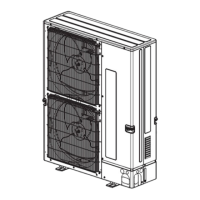
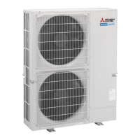
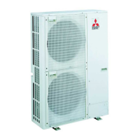
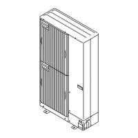
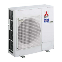
Outdoor unit
[Model Name]
PUHZ-P200YKA3
PUHZ-P250YKA3
[Service Ref.]
PUHZ-P200YKA3.UK
PUHZ-P250YKA3.UK
PARTS CATALOG (OCB679)
CONTENTS
1. REFERENCE MANUAL ·································2
2. SAFETY PRECAUTION ································· 2
3. FEATURES ·····················································6
4. SPECIFICATIONS ·········································· 7
5. DATA ······························································· 8
6. OUTLINES AND DIMENSIONS ··················· 11
7. WIRING DIAGRAM ······································12
8. WIRING SPECIFICATIONS ··························13
9.
REFRIGERANT SYSTEM DIAGRAM
·············18
10. TROUBLESHOOTING ··································20
11. FUNCTION SETTING ··································· 74
12.
MONITORING THE OPERATION DATA BY THE REMOTE CONTROLLER
···· 83
13. EASY MAINTENANCE FUNCTION ·············92
14. DISASSEMBLY PROCEDURE ·····················95
Note:
•Thismanualdescribesservice
dataoftheoutdoorunitsonly.
No. OCH679
November 2017