Do you have a question about the Mitsubishi Electric PUHZ-P200YKAR1.UK and is the answer not in the manual?
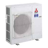
| Brand | Mitsubishi Electric |
|---|---|
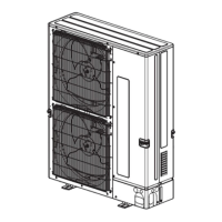
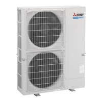
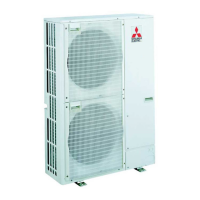
| Model | PUHZ-P200YKAR1.UK |
| Category | Air Conditioner |
| Language | English |
Power wiring specifications and circuit rating.
Actions for recurring and non-recurring troubles.
Checking and resetting error information on the remote controller.
Steps for proceeding with self-diagnosis.
Performing self-diagnosis using remote controller.
Self-diagnosis in case of trouble during operation.
Error codes and symptoms detected by indoor unit.
Error codes and symptoms detected by outdoor unit.
Actions for power-on abnormalities.
Abnormalities detected during unit operation.
Troubleshooting common remote controller display issues.
Diagnosis flow for "PLEASE WAIT" display.
Diagnosis flow for no remote controller display.
Setting unit functions via remote controller.
Selecting functions via wired remote controller.
Selecting functions via wireless remote controller.
Smooth maintenance procedure for remote controller models.
Smooth maintenance procedure for remote controller models.