EasyManua.ls Logo

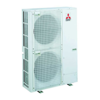
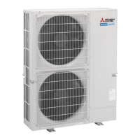
Mitsubishi Electric PUHZ-P200YHA3 User Manual

Mitsubishi Electric PUHZ-P200YHA3
94 pages
To Next Page IconTo Next Page
Page #1 background imageLoading...
Page #1 background image
SERVICE MANUAL
No. OCH424
REVISED EDITION-E
SPLIT-TYPE, HEAT PUMP AIR CONDITIONERS
R410A
October 2011
Outdoor unit
[Model names]
PUHZ-P200YHA
PUHZ-P250YHA
PUHZ-P200YHA3
PUHZ-P250YHA3
[Service Ref.]
PUHZ-P200YHA
PUHZ-P250YHA
PUHZ-P200YHA3
PUHZ-P200YHA3R1
PUHZ-P200YHA3R2
PUHZ-P200YHA3R3
PUHZ-P250YHA3
PUHZ-P250YHA3R1
PUHZ-P250YHA3R2
PUHZ-P250YHA3R3
PUHZ-P200YHA3R1/R2/R3
PUHZ-P250YHA3R1/R2/R3
Note:
This manual describes only
service data of the outdoor units.
RoHS compliant products have
<G> mark on the spec name plate.
CONTENTS
1. TECHNICAL CHANGES
.................................
2
2. REFERENCE MANUAL
..................................
2
3. SAFETY PRECAUTION
..................................
3
4. FEATURES
......................................................
6
5. SPECIFICATIONS
...........................................
7
6. DATA
...............................................................
8
7. OUTLINES AND DIMENSIONS
....................
10
8. WIRING DIAGRAM
.......................................
12
9. WIRING SPECIFICATIONS
..........................
13
10.
REFRIGERANT SYSTEM DIAGRAM
...............
18
11. TROUBLESHOOTING
...................................
20
12. FUNCTION SETTING
....................................
70
13.
MONITORING THE OPERATION DATA BY THE REMOTE CONTROLLER
....
77
14. EASY MAINTENANCE FUNCTION
..............
87
15. DISASSEMBLY PROCEDURE
.....................
90
PARTS CATALOG (OCB424)
Revision:
"11-10 FUNCTION OF SWITCHES,
CONNECTORS AND JUMPERS"
has been modified in REVISED
EDITION-E. (See page 65)
Some descriptions have been
modified.
Please void OCH424
REVISED EDITION-D.

Other manuals for Mitsubishi Electric PUHZ-P200YHA3

Questions and Answers:

Mitsubishi Electric PUHZ-P200YHA3 Specifications

General IconGeneral
Cooling Capacity20.0 kW
Heating Capacity22.4 kW
RefrigerantR410A
Sound Power Level Heating72 dB(A)
Sound Pressure Level (Outdoor Unit)52 dB(A)
Power Supply400V, 3-phase, 50Hz

Summary

TECHNICAL CHANGES

SAFETY PRECAUTIONS

ALWAYS OBSERVE FOR SAFETY

General safety guidelines for all repair services.

CAUTIONS RELATED TO NEW REFRIGERANT R410A

Specific safety measures for using R410A refrigerant.

PRODUCT FEATURES

TECHNICAL SPECIFICATIONS

OPERATIONAL DATA

REFILLING REFRIGERANT CHARGE

Specifies refrigerant charge amounts based on piping length.

COMPRESSOR TECHNICAL DATA

Details technical specifications for the compressor.

NOISE CRITERION CURVES

Presents sound pressure level data across frequency bands.

OUTLINES AND DIMENSIONS

UNIT INSTALLATION SPACING REQUIREMENTS

Specifies required free and service space around the unit.

FOUNDATION AND PIPING-WIRING GUIDELINES

Instructions for foundation bolts and piping/wiring directions.

WIRING DIAGRAMS

WIRING SPECIFICATIONS

FIELD ELECTRICAL WIRING (POWER)

Details power wiring specifications for installation.

REFRIGERANT SYSTEM DIAGRAMS

TROUBLESHOOTING GUIDE

TROUBLESHOOTING SUMMARY

Overview of error code display and corrective actions.

TEST RUN CHECKPOINTS

Essential checks to perform before initiating a test run.

SELF-DIAGNOSIS PROCEDURES

Methods for accessing and interpreting unit self-diagnosis data.

OPERATION PROBLEM DIAGNOSIS

How to diagnose issues that occur during unit operation.

MAINTENANCE AND SERVICE DIAGNOSIS

Procedures for performing self-diagnosis during maintenance.

REMOTE CONTROLLER DIAGNOSIS

Steps to diagnose issues with the remote controller.

WIRELESS REMOTE MALFUNCTION DIAGNOSIS

Method for diagnosing malfunctions via wireless remote.

ERROR CODE PATTERNS AND DETECTION

Classifies errors by indoor/outdoor unit output patterns.

SELF-DIAGNOSIS ACTION TABLE

Table detailing actions for specific self-diagnosis errors.

TROUBLESHOOTING BY SYMPTOMS

Guides troubleshooting based on observed operational phenomena.

CUSTOMER CALL TOPICS

UNIT OPERATION AND REMOTE CONTROLLER ISSUES

Common customer complaints regarding unit startup and remote control.

COOLING/HEATING PERFORMANCE ISSUES

Troubleshooting insufficient cooling or heating capacity.

AIR CONDITIONER SOUND DESCRIPTIONS

Explains normal operational sounds from the unit.

BLOWER AND AIRFLOW DIRECTION PROBLEMS

Addresses issues related to fan operation and airflow direction.

COMPONENT CHECK PROCEDURES

LINEAR EXPANSION VALVE CHECK

Detailed steps for checking the linear expansion valve component.

EMERGENCY OPERATION GUIDELINES

OUTDOOR CONTROLLER CIRCUIT BOARD DETAILS

NOISE FILTER CIRCUIT BOARD INFORMATION

Details on the outdoor noise filter circuit board.

POWER CIRCUIT BOARD INFORMATION

Details on the outdoor power circuit board.

SWITCHES, CONNECTORS, AND JUMPERS FUNCTIONS

FUNCTION OF SWITCHES

Explains the operation and effects of various switches.

SPECIAL FUNCTIONS

Details on special operational modes like low-sound priority.

ON DEMAND CONTROL WIRING

Instructions for wiring demand control input.

UNIT FUNCTION SETTINGS

UNIT FUNCTION SETTING BY REMOTE CONTROLLER

Guide to configuring unit functions using the remote controller.

WIRED REMOTE CONTROLLER FUNCTION SELECTION

Procedure for selecting functions using a wired remote controller.

WIRELESS REMOTE CONTROLLER FUNCTION SELECTION

Procedure for selecting functions using a wireless remote controller.

REMOTE CONTROLLER FUNCTION SELECTION

OPERATION DATA MONITORING

HOW TO MONITOR OPERATION DATA

Steps to access and view operational data using the remote controller.

REQUEST CODE LIST

OPERATION AND CONTROL STATES

Request codes for unit operational and control status.

FAN AND ACTUATOR CONTROL STATES

Request codes for fan and actuator output states.

ERROR CONTENT CODES

Request codes indicating specific error conditions.

EXTERNAL INPUT AND SETTING INFORMATION

Request codes for external inputs and unit settings.

OUTDOOR UNIT SWITCH SETTINGS

Details of DIP switch configurations for outdoor units.

INDOOR UNIT MODEL AND CAPACITY SETTINGS

Request codes for indoor unit model and capacity configuration.

EASY MAINTENANCE FUNCTION

MAINTENANCE MODE OPERATION METHOD

Guide to activating and using maintenance mode.

GUIDE FOR OPERATION CONDITION

Procedure for checking operation conditions and diagnosing performance.

DISASSEMBLY PROCEDURES

SERVICE PANEL AND TOP PANEL REMOVAL

Steps for removing the outer service and top panels.

FAN MOTOR REMOVAL

Instructions for removing the fan motor components.

ELECTRICAL PARTS BOX REMOVAL

Steps for accessing and removing the electrical parts box.

THERMISTOR REMOVAL

Procedures for removing various thermistor sensors.

VALVE AND SWITCH REMOVAL

Steps for removing 4-way valves, expansion valves, and pressure switches.

COMPRESSOR AND ACCUMULATOR REMOVAL

Procedures for removing the compressor and accumulator.

Related product manuals