EasyManua.ls Logo

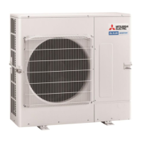
Mitsubishi Electric PUHZ-P125YHA User Manual

Mitsubishi Electric PUHZ-P125YHA
138 pages
To Next Page IconTo Next Page
Page #1 background imageLoading...
Page #1 background image
SERVICE MANUAL
No.OCH415
REVISED EDITION-G
R410A
July 2013
PUHZ-P100VHA4.UK
PUHZ-P100YHA2.UK
CONTENTS
1. TECHNICAL CHANGES
................................
2
2. REFERENCE MANUAL
.................................
3
3. SAFETY PRECAUTION
.................................
3
4. FEATURES
.....................................................
7
5. SPECIFICATIONS
..........................................
8
6. DATA
.............................................................
12
7. OUTLINES AND DIMENSIONS
...................
15
8. WIRING DIAGRAM
......................................
23
9. WIRING SPECIFICATIONS
..........................
30
10.
REFRIGERANT SYSTEM DIAGRAM
..............
35
11. TROUBLESHOOTING
..................................
38
12. FUNCTION SETTING
.................................
101
13. EASY MAINTENANCE FUNCTION
...........
114
14.
MONITORING THE OPERATION DATA BY THE REMOTE CONTROLLER
..
118
15. DISASSEMBLY PROCEDURE
...................
129
PARTS CATALOG (OCB415)
Outdoor unit
[Model names]
PUHZ-P100VHA2
PUHZ-P125VHA2
PUHZ-P140VHA2
PUHZ-P100VHA3
PUHZ-P125VHA3
PUHZ-P140VHA3
PUHZ-P100VHA4
PUHZ-P100YHA
PUHZ-P100YHA2
PUHZ-P125YHA
PUHZ-P140YHA
[Service Ref.]
Refer to page 2.
Note:
RoHS compliant products have
<G> mark on the spec name
plate.
Revision:
PUHZ-P100YHA2R1.UK
has been added in REVISED
EDITION-G.
Some descriptions have been
modified.
Please void OCH415
REVISED EDITION-F.
SPLIT-TYPE, HEAT PUMP AIR CONDITIONERS

Table of Contents

Other manuals for Mitsubishi Electric PUHZ-P125YHA

Questions and Answers:

Mitsubishi Electric PUHZ-P125YHA Specifications

General IconGeneral
BrandMitsubishi Electric
ModelPUHZ-P125YHA
CategoryAir Conditioner
LanguageEnglish

Summary

SERVICE MANUAL

Outdoor unit [Model names]

Lists model names for outdoor units covered in the service manual.

CONTENTS

Provides a detailed list of sections and their corresponding page numbers.

Revision

Details the changes and updates in the revised edition of the manual.

Note

Contains information regarding RoHS compliant products.

1 TECHNICAL CHANGES

2 REFERENCE MANUAL

3 SAFETY PRECAUTION

3-1. ALWAYS OBSERVE FOR SAFETY

Emphasizes critical safety measures to be followed before and during repair services.

3-2. CAUTIONS RELATED TO NEW REFRIGERANT

[1] Cautions for service

[2] Additional refrigerant charge

[3] Service tools

Cautions for refrigerant piping work

1 Thickness of pipes

Specifies the required thickness of refrigerant piping for R410A.

2 Dimensions of flare cutting and flare nut

Details the flare cutting dimensions and flare nut specifications for R410A.

3 Tools for R410A

Presents a table comparing the usability of R410A tools with conventional tools.

4 FEATURES

CHARGELESS SYSTEM

5 SPECIFICATIONS

6 DATA

6-1. REFILLING REFRIGERANT CHARGE (R410A : kg)

Provides data for refilling refrigerant charge based on piping length.

6-2. COMPRESSOR TECHNICAL DATA

Lists technical data for compressors, including winding resistance.

6-3. NOISE CRITERION CURVES

6-4. STANDARD OPERATION DATA

7 OUTLINES AND DIMENSIONS

1 FREE SPACE (Around the unit)

Specifies the required free space around the outdoor unit for installation.

2 SERVICE SPACE

Details the necessary space for servicing the outdoor unit.

3 FOUNDATION BOLTS

Explains the requirement and method for securing the unit with foundation bolts.

4 PIPING-WIRING DIRECTIONS

Illustrates the directions for piping and wiring connections.

8 WIRING DIAGRAM

1 MODEL SELECT

Details how to select the model using DIP switches SW5 and SW6.

9 WIRING SPECIFICATIONS

9-1. FIELD ELECTRICAL WIRING (power wiring specifications)

Provides tables for power wiring specifications based on unit models and voltage.

9-2. SEPARATE INDOOR UNIT/OUTDOOR UNIT POWER SUPPLIES

9-3. INDOOR – OUTDOOR CONNECTING CABLE

9-4. M-NET WIRING METHOD

9-4-1. M-NET address setting

Explains how to set M-NET addresses using rotary switches.

9-4-2. Refrigerant address setting

Details setting refrigerant addresses using DIP switches.

9-4-3. Regulations in address settings

Provides regulations for address settings in multiple grouping systems.

10 REFRIGERANT SYSTEM DIAGRAM

10-1. REFRIGERANT COLLECTING (PUMP DOWN)

10-2. START AND FINISH OF TEST RUN

11 TROUBLESHOOTING

11-1. TROUBLESHOOTING

Summarizes error codes and actions for recurring or non-recurring troubles.

11-2. CHECK POINT UNDER TEST RUN

Lists checkpoints to verify before and during a test run.

11-2-2. Test run for wired remote controller <PAR-31MAA>

<Error information>

<Checking the error information>

<Error history>

Explains how to view error history records.

Deleting the error history

Provides steps to delete error history records.

11-2-3. Test run for wired remote controller <PAR-21MAA>

11-2-4. Test run for wireless remote controller

11-3. HOW TO PROCEED "SELF-DIAGNOSIS"

11-3-1. Self-diagnosis <PAR-31MAA>

Details the self-diagnosis procedure for the PAR-31MAA remote controller.

11-3-2. Remote controller check <PAR-31MAA>

11-3-3. Self-diagnosis <PAR-21MAA>

11-3-4. Self-Diagnosis During Maintenance or Service <PAR-21MAA>

11-3-5. Remote controller check <PAR-21MAA>

11-3-6. Self-diagnosis <Wireless remote controller>

[Output pattern A] Errors detected by indoor unit

[Output pattern B] Errors detected by unit other than indoor unit (outdoor unit, etc.)

11-4. SELF-DIAGNOSIS ACTION TABLE

<Abnormalities detected while unit is operating>

11-5. TROUBLESHOOTING OF PROBLEMS

Phone Calls From Customers

Symptoms: “PLEASE WAIT” is kept being displayed on the remote controller.

Symptoms: Nothing is displayed on the remote controller

Phone Calls From Customers

Sound comes out from the air conditioner.

Something is wrong with the blower…..

Something is wrong with the airflow direction….

Phone Calls From Customers

11-6. HOW TO CHECK THE PARTS

Check method of DC fan motor (fan motor/outdoor controller circuit board)

11-7. HOW TO CHECK THE COMPONENTS

Linear expansion valve

(3) How to attach and detach the coil of linear expansion valve

11-8. EMERGENCY OPERATION

(5) Operation data during emergency operation

11-9. TEST POINT DIAGRAM

Outdoor noise filter circuit board

Outdoor power circuit board

Active filter module

11-10. FUNCTION OF SWITCHES, CONNECTORS AND JUMPERS

(1) Function of switches

Explains the functions of DIP switches like compulsory defrosting and test run.

(2) Function of connectors and switches

Special function

Explains special functions like low-level sound priority mode and demand control.

<Display function of inspection for outdoor unit>

Indication Error

<Outdoor unit operation monitor function>

SW2 setting

12 FUNCTION SETTING

12-1. UNIT FUNCTION SETTING BY THE REMOTE CONTROLLER

Details function settings available via the remote controller.

12-1-1. Selecting functions using the wired remote controller <PAR-31MAA>

<Function setting>

12-1-2. Selecting functions using the wired remote controller <PAR-21MAA>

[Operating Procedure]

12-1-3. Selecting functions using the wireless remote controller (Type C)

12-2. FUNCTION SELECTION OF REMOTE CONTROLLER

12-2-1. PAR-31MAA

Details function selection for the PAR-31MAA remote controller.

<Menu structure of PAR-31MAA>

<Main menu list of PAR-31MAA>

12-2-2. PAR-21MAA

[Function selection flowchart]

13 EASY MAINTENANCE FUNCTION

13-1. SMOOTH MAINTENANCE

Explains the smooth maintenance function for viewing operational data.

13-1-1. PAR-31MAA

Details the smooth maintenance function for the PAR-31MAA.

13-2. MAINTENANCE MODE OPERATION METHOD

Data measurement

13-3. GUIDE FOR OPERATION CONDITION

14 MONITORING THE OPERATION DATA BY THE REMOTE CONTROLLER

14-1. HOW TO "MONITOR THE OPERATION DATA"

Details the procedure for monitoring operational data via the remote controller.

14-1-1. PAR-31MAA

Explains monitoring operation data for the PAR-31MAA.

14-1-2. PAR-21MAA

14-2. REQUEST CODE LIST

14-2-1. Detail Contents in Request Code

[Outdoor unit switch setting display (SW1 to SW10, except SW3)]

[Indoor unit – Model setting information]

[Indoor unit – Capacity setting information]

[Wireless pair No. (indoor control board side) setting]

15 DISASSEMBLY PROCEDURE

1. Removing the service panel and top panel

Details the removal of the service panel and top panel.

2. Removing the fan motor (MF1)

Explains the procedure for removing the fan motor.

3. Removing the control box

Details the steps for removing the control box.

4. Removing the thermistor <Outdoor 2-Phase Pipe> (TH6)

5. Removing the thermistor <Ambient> (TH7)

6. Removing the thermistor <Outdoor pipe> (TH3), thermistor <Discharge> (TH4) and thermistor <Comp.Surface>(TH32)

7. Removing the 4-way valve coil (21S4), and LEV coil (LEV(A))

8. Removing the 4-way valve

9. Removing LEV

10. Removing bypass valve coil (SV) and bypass valve

11. Removing the high pressure switch (63H)

12. Removing the reactor (DCL)

13. Removing the motor for compressor (MC)

14. Removing the accumulator

1. Removing the service panel and top panel

2. Removing the fan motor (MF1, MF2)

3. Removing the control box

4. Removing the thermistor <Outdoor 2-Phase Pipe> (TH6)

5. Removing the thermistor <Ambient> (TH7)

6. Removing the thermistor <Outdoor pipe> (TH3), thermistor <Discharge> (TH4) and thermistor <Comp.Surface>(TH32)

7. Removing the 4-way valve coil (21S4), and LEV coil (LEV(A))

8. Removing the 4-way valve

9. Removing LEV

10. Removing bypass valve coil (SV) and bypass valve

11. Removing the high pressure switch (63H)

12. Removing the reactor (DCL)

13. Removing the motor for compressor (MC)

14. Removing the accumulator

Related product manuals