129
15 DISASSEMBLY PROCEDURE
OPERATING PROCEDURE
PHOTOS & ILLUSTRATION
PUHZ-P100VHA2.UK PUHZ-P100VHA3.UK PUHZ-P100VHA3R1.UK
PUHZ-P100VHA3R2.UK PUHZ-P100VHA4.UK
PUHZ-P100YHA.UK PUHZ-P100YHAR1.UK
PUHZ-P100YHA2.UK PUHZ-P100YHA2R1.UK
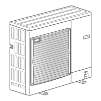
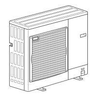
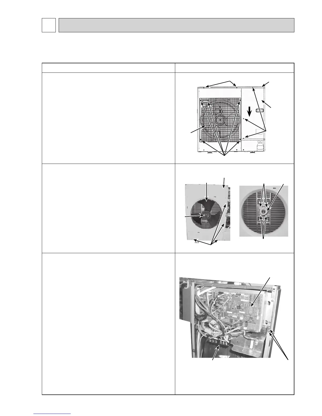
1. Removing the service panel and top panel
(1) Remove 3 service panel fixing screws (5 × 12) and slide
the hook on the right downward to remove the service
panel.
(2) Remove screws (2 for front, 3 for rear/5 × 12) of the top
panel and remove it.
Figure 1
Top panel fixing screws
Top panel
Service panel
fixing screws
Service panel
Grill fixing screws
Fan grille
2. Removing the fan motor (MF1)
(1) Remove the service panel. (See Figure 1)
(2) Remove the top panel. (See Figure 1)
(3) Remove 5 fan grille fixing screws (5 × 12) to detach the
fan grille. (See Figure 1)
(4) Remove a nut (for right handed screw of M6) to detach the
propeller. (See Photo 1)
(5) Disconnect the connector CNF1 on the controller circuit
board in the control box.
(6) Loosen 3 clamps on the separator and motor support, then
unbind the lead wires.
(7) Remove 4 fan motor fixing screws (5 × 20) to detach the
fan motor. (See Photo 2)
Fan motor fixing screws
Photo 3 (PUHZ-P100V)
Photo 1
Fan
motor
(MF1)
Fan motor
fixing screws
Propeller
Front panel
Front panel fixing screws
Nut
Photo 2
Slide
3. Removing the control box
(1) Remove the service panel. (See Figure 1)
(2) Remove the top panel. (See Figure 1)
(3) Disconnect the indoor/outdoor connecting wire and the
power supply wire from the terminal block.
(4) Disconnect the connector CNF1 and LEV-A on the
controller circuit board.
<Symbols on the board>
• CNF1 : Fan motor
• LEV-A : LEV
(5) Disconnect the pipe-side connections of the following parts.
• Thermistor <Outdoor Pipe>, <Liquid> (TH3)
• Thermistor <Discharge> (TH4) (VHA2, VHA3(R1))
• Thermistor <Comp.Surface> (TH32) (VHA3R2, VHA4,
YHA(R1), YHA2(R1))
• Thermistor <Outdoor 2-Phase Pipe, Outdoor>,
<2-Phase Pipe, Ambient> (TH6/7)
• High pressure switch (63H)
• 4-way valve coil (21S4)
(6) Remove the terminal cover and disconnect the compressor
lead wire.
(7) Loosen the clamp on the separator and unbind the lead
wires.
(8) Remove 2 control box fixing screws (4 × 10) and detach
the control box by pulling it upward. The control box is
fixed with 2 hooks on the left and 1 hook on the right.
Controller circuit
board (C.B.)
Terminal block (TB1)
Control box
fixing screws
Continued to the next page.
 Loading...