S
Sherry FisherSep 5, 2025
What to do if my Mitsubishi Electric Air Conditioner has ACCT sensor abnormality?
- AAmanda FloresSep 5, 2025
If your Mitsubishi Electric Air Conditioner is showing an ACCT sensor abnormality, check Code List 5301.
What to do if my Mitsubishi Electric Air Conditioner has ACCT sensor abnormality?
If your Mitsubishi Electric Air Conditioner is showing an ACCT sensor abnormality, check Code List 5301.
What to do if my Mitsubishi Electric PURY-P450 shows Bus Voltage abnormality (H/W detect)?
If your Mitsubishi Electric Air Conditioner displays a Bus Voltage abnormality (H/W detect), check Code List 4230.
What to do if my Mitsubishi Electric PURY-P450 Air Conditioner has a high pressure sensor abnormality (Outdoor unit HPS / BC controller 63HS)?
If you're encountering a high pressure sensor abnormality (Outdoor unit HPS / BC controller 63HS) with your Mitsubishi Electric Air Conditioner, check Code List 5201.
What to do if my Mitsubishi Electric Air Conditioner shows over-current protection?
If your Mitsubishi Electric Air Conditioner is showing an over-current protection error, check Code List 4108.
What to do if my Mitsubishi Electric PURY-P450 Air Conditioner shows drain sensor abnormality?
If your Mitsubishi Electric Air Conditioner displays a drain sensor abnormality, check Code List 2503.
What to do if my Mitsubishi Electric PURY-P450 has IPM abnormality?
If your Mitsubishi Electric Air Conditioner is showing an IPM abnormality, check Code List 4250.
What to do if my Mitsubishi Electric PURY-P450 has low pressure abnormality (OC)?
If your Mitsubishi Electric Air Conditioner is showing a low pressure abnormality (OC), check Code List 1301.
What to do if my Mitsubishi Electric PURY-P450 Air Conditioner has a cooling fan abnormality?
If your Mitsubishi Electric Air Conditioner is experiencing a cooling fan abnormality, check Code List 4260.
What to do if my Mitsubishi Electric Air Conditioner has an overcharged refrigerant abnormality?
If you suspect an overcharged refrigerant abnormality in your Mitsubishi Electric Air Conditioner, check Code List 1500.
What to do if my Mitsubishi Electric PURY-P450 shows high pressure abnormality (OC)?
If your Mitsubishi Electric Air Conditioner displays a high pressure abnormality (OC), check Code List 1302.
| Cooling Capacity | 45.0 kW |
|---|---|
| Heating Capacity | 50.0 kW |
| Refrigerant | R410A |
| Sound Pressure Level (Outdoor Unit) | 62 dB(A) |
| Power Supply | 3-phase, 380-415V, 50Hz |
Explanation of warning and caution symbols used in the manual text.
Explanation of symbols used in diagrams and illustrations.
Key items to verify before commencing service work on the unit.
Tools required specifically for R410A systems, not interchangeable.
Tools usable with R410A, but with specific limitations or requirements.
Tools compatible with both R22/R407C and R410A systems.
Tools that must not be used with R410A systems due to incompatibility.
Guidelines for storing refrigerant piping material indoors to prevent contamination.
Instructions on sealing piping ends to protect against moisture and dirt.
Requirement for a vacuum pump with a check valve to prevent oil backflow.
Specifies the required vacuum level and pump maintenance.
Details the necessary accuracy for the vacuum gauge.
Recommended duration for evacuation process.
Steps to prevent oil backflow when stopping the vacuum pump.
Using a vacuum pump with a reverse-flow check valve to prevent oil backflow.
Specifies vacuum degree requirements and pump maintenance.
Details the necessary vacuum gauge accuracy.
Recommended evacuation duration for thorough drying.
Correct procedure for stopping the vacuum pump to prevent issues.
Procedure for special vacuum drying when standard methods are insufficient.
Compares chemical properties of R410A with conventional refrigerants.
Details the composition of different refrigerants.
Compares pressure characteristics of R410A and R22.
Specifies the type of oil used with HFC refrigerants and its characteristics.
Explains how contaminants affect refrigerating machine oil and the system.
Guidelines for electrical work and M-NET control system wiring and setup.
Information on setting DIP switches for unit configuration.
Details on setting addresses for various controllers and units.
Wiring diagrams and configurations for systems using MA remote controllers.
Wiring configuration for M-NET systems with centralized control.
Details on piping configuration for line-branch systems.
Specifications for refrigerant pipe diameters based on unit capacity.
Procedures for connecting BC controllers to outdoor units and indoor units.
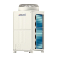
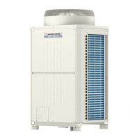
Visual identification of outdoor unit components and refrigerant circuit layout.
Description of the main circuit board components and connectors.
Details on the inverter board components and connections.
Information on the FAN board components and connections.
Description of the relay board components and functions.
Details on the second relay board components and functions.
Information on the filter board components and connections.
Details on the G/A board components and functions.
Comparison of features between MA and M-NET remote controllers.
Guidance on choosing between MA and M-NET controllers for optimal system performance.
Procedure for setting groups and interlocks using an ME remote controller.
How to select and change the operation mode display.
Options for selecting room temperature display or no display.
How to set temperature range limits for cooling and heating.
Specific steps for interlocking Lossnay units with the MA remote controller.
How to select the temperature sensor source for the indoor unit.
Electrical wiring diagram for specific PURY model series.
Electrical wiring diagram for specific PURY model series.
Electrical wiring diagram for CMB-P104V-G.
Electrical wiring diagram for CMB-P105, 106V-G.
Electrical wiring diagram for CMB-P108, 1010V-G.
Electrical wiring diagram for CMB-P1013, 1016V-G.
Electrical wiring diagram for CMB-P104V-GB.
Electrical wiring diagram for CMB-P108V-GB.
Electrical wiring diagram for CMB-P108, 1010V-GA.
Electrical wiring diagram for CMB-P1013, 1016V-GA.
Diagram illustrating the refrigerant flow path within the system.
Description of the functions and specifications of outdoor unit components.
Description of the functions and specifications of indoor unit components.
Functions of the BC controller, including G type specifics.
Functions and specifications specific to the GA type BC controller.
Functions and specifications specific to the GB type BC controller.
Dip switch settings for the outdoor unit and main board.
Dip switch settings for the inverter board.
Dip switch settings for the fan board.
DIP switch settings for indoor units, including model and capacity selection.
DIP switch settings for the BC controller main board.
Switch settings for remote controllers, including main/sub and display options.
Initial sequence and priority of operations when the unit is powered on.
Control parameters during the initial start-up phase.
Operation of bypass solenoid valves (SV1, SV2, SV3) for pressure regulation.
How compressor frequency is controlled based on system demands.
Procedures and conditions for initiating and completing defrost operations.
Steps for recovering refrigerant to prevent accumulation in indoor units.
Control methods for the outdoor unit fan speed and operation.
Available operation modes for indoor units (cooling, heating, dry, fan, stop).
Available operation modes for outdoor units.
How the system automatically switches between cooling and heating modes.
How operation modes affect system load capacity.
Control logic for solenoid valves A, B, and C based on operating mode.
Control logic for SVM1 based on operating mode.
Control logic for LEV based on operation mode and superheat.
Control logic for SVM2, specific to GA type units.
Flowchart detailing how the indoor unit determines its operation mode.
Flowchart for outdoor unit operations in various modes.
Flowchart for BC controller operations in various modes.
Detailed steps and checks for cooling operation.
Detailed steps and checks for heating operation.
Detailed steps and checks for dry operation.
Essential checks before performing a test run on the unit.
Step-by-step procedure for conducting a test run.
Relationship between operating conditions and refrigerant amount.
Symptoms indicating excess or lack of refrigerant.
How to check and judge refrigerant volume based on operating conditions.
Steps for entering and performing refrigerant volume adjustment.
Reference data for cooling operations under standard conditions.
Reference data for heating operations under standard conditions.
List of error codes, their meanings, and detection methods.
List of fault codes specific to intermittent issues in outdoor units.
Procedures for responding to error messages displayed on the remote controller.
Troubleshooting steps for MA remote controller malfunctions.
Troubleshooting steps for M-NET remote controller malfunctions.
Troubleshooting common to both MA and M-NET remote controllers.
How noise affects MA remote control transmission.
Verifying MA remote control transmission specifications and waveforms.
Analyzing M-NET transmission wave shapes and noise issues.
Procedures for checking and mitigating noise issues.
Methods for diagnosing and troubleshooting pressure sensor failures.
Specific troubleshooting steps for the low-pressure sensor.
Troubleshooting procedures for solenoid valves (SV1, SV2, SV3, SV4, SV5).
Troubleshooting heat exchanger capacity control solenoid valves.
Troubleshooting steps for the 4-way switching valve.
Checking the function and flow through check valve blocks.
Troubleshooting fan motor issues, including speed control and abnormal operation.
Flowchart for diagnosing pressure sensor issues on the BC controller.
Troubleshooting procedures for thermistor sensors used by the BC controller.
Flowchart for diagnosing LEV and solenoid valve issues.
Troubleshooting steps for solenoid valves SVA, SVB, and SVC.
Checking the BC controller transformer for proper operation.
Understanding LEV operation and troubleshooting using pulse signals.
Methods for judging LEV operation and identifying failure modes.
Identifying and resolving inverter-related defects and compressor issues.
Steps to take when the main power breaker trips.
Procedures for checking individual components of the main inverter circuit.
Checking the IPM module for proper resistance and function.
Checking the diode stack for resistance and proper function.
Precautions for replacing inverter components, including wiring and grease application.
Overview of the control power source and its function blocks.
Procedure for finding refrigerant leaks in indoor unit extended piping during cooling.
Procedure for finding refrigerant leaks in the outdoor unit during cooling.
Procedure for finding refrigerant leaks in indoor unit extended piping during heating.
Procedure for finding refrigerant leaks in the outdoor unit during heating.
Steps for removing and replacing the service panel.
Procedures for accessing and checking the control box components.
Replacing thermistors for liquid and gas pipe temperature detection.
Replacing pressure sensors on the BC controller.
Replacing LEV components on the BC controller.
Replacing solenoid valves on the BC controller.
How to read and interpret the LED monitor display.
Functionality related to storing time data and system controller time settings.
Table detailing LED codes and their corresponding meanings for monitoring.