T
Timothy Valencia DDSAug 27, 2025
What to do if my Mitsubishi Electric Air Conditioner has a drain pump abnormality?
- FfhollowayAug 27, 2025
If your Mitsubishi Electric Air Conditioner is showing a drain pump abnormality, check Code List 2502.
What to do if my Mitsubishi Electric Air Conditioner has a drain pump abnormality?
If your Mitsubishi Electric Air Conditioner is showing a drain pump abnormality, check Code List 2502.
What to do if my Mitsubishi Electric PURY-P650YGM-A displays a thermal sensor abnormality?
If your Mitsubishi Electric Air Conditioner shows a thermal sensor abnormality, check Code List 5101.
What to do if my Mitsubishi Electric PURY-P650YGM-A Air Conditioner shows fan speed abnormality (motor abnormality) (IC, LC)?
If you're encountering a fan speed abnormality (motor abnormality) (IC, LC) with your Mitsubishi Electric Air Conditioner, check Code List 4116.
What to do if my Mitsubishi Electric PURY-P650YGM-A Air Conditioner is leaking water (LC)?
If you are experiencing water leakage (LC) with your Mitsubishi Electric Air Conditioner, check Code List 2600.
What to do if my Mitsubishi Electric Air Conditioner has a water leakage abnormality?
If you notice a water leakage abnormality with your Mitsubishi Electric Air Conditioner, check Code List 2500.
| Series | PURY-P |
|---|---|
| Power Source | Electric |
| Refrigerant | R410A |
| Type | Air Conditioner |
| Power Supply | 380-415V, 50Hz |
| Operating Temperature Range (Cooling) | -5 to 46 °C |
| Operating Temperature Range (Heating) | -15°C to 24°C |
Explains text symbols like Warning, Caution, and action indicators.
Explains illustration symbols like avoid action, important instructions, grounding, and electric shock warning.
Emphasizes reading and following labels affixed to the main unit for safety.
Specific safety guidelines for handling units that use R410A refrigerant.
Lists essential checks before starting any servicing procedure.
Describes types of copper pipes (Type-O, Type-1/2H) and their characteristics.
Specifies recommended radial thickness for copper pipes based on refrigerant and pressure.
Guidelines for storing piping material indoors to prevent contamination.
Instructions on sealing pipe ends to prevent moisture and dirt ingress.
Compares chemical properties of R410A, R407C, and R22 refrigerants.
Discusses the composition of R410A and handling of vapor phase removal.
Details pressure differences in R410A units compared to R22 units.
Explains the difference in oil used for HFC refrigerants vs. R22 systems.
Details how air, moisture, and contaminants affect refrigerating machine oil.
Guidelines for electrical work and M-NET control wiring.
Describes wiring for systems with a centralized controller.
Details end connection piping sizes for BC controllers based on indoor unit types.
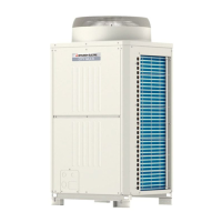
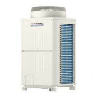
Illustrates the external view and internal refrigerant circuit of outdoor units.
Shows the appearance and internal components of the control box.
Details the main circuit board and other boards within the control box.
Illustrates the front and rear views of the BC controller panel.
Shows the BC control box and its components.
Illustrates the BC controller board and its switches.
Compares functions and specifications of MA and M-NET remote controllers.
Explains group and interlock settings using an ME remote controller.
Instructions on switching to the built-in thermo on the remote controller.
Provides the electrical wiring diagram for specific outdoor unit models.
Provides the electrical wiring diagram for specific outdoor unit models.
Shows the electrical wiring diagram for CMB-P104V-G.
Shows the electrical wiring diagram for CMB-P105, 106V-G.
Shows the electrical wiring diagram for CMB-P108, 1010V-G.
Shows the electrical wiring diagram for CMB-P1013, 1016V-G.
Shows the electrical wiring diagram for CMB-P104V-GB.
Shows the electrical wiring diagram for CMB-P108V-GB.
Shows the electrical wiring diagram for CMB-P108, 1010V-GA.
Shows the electrical wiring diagram for CMB-P1013, 1016V-GA.
Illustrates the refrigerant flow for specific outdoor unit models.
Describes the functions and specifications of outdoor unit components.
Describes the functions and specifications of indoor unit components.
Details the functions and specifications of BC controller components.
Explains the functions and default settings of outdoor unit dip switches.
Details DIP switch settings for indoor units based on model and capacity.
Explains switch settings for the BC controller main board.
Describes switch settings for remote controllers.
Describes the initial microcomputer processing upon power-on.
Explains the start-up sequence and frequency control.
Shows simplified diagrams of the refrigerant circuit in different modes.
Illustrates the refrigerant cycle path in simplified diagrams.
Lists the five available operation modes for indoor units.
Lists the five available operation modes for outdoor units.
Describes how the system automatically selects cooling or heating modes.
Shows the relationship between operation modes and system load capacity.
Explains the control logic for solenoid valves SVA, SVB, and SVC.
Details the ON/OFF control logic for SVM1 based on operation mode.
Explains how LEV opening is controlled based on operation mode and superheat.
Details the control logic for SVM2 (Type GA only).
Illustrates the logic for determining the operational mode for indoor units.
Details the operation flow for outdoor units in various modes.
Shows the operation flow for the BC controller.
Describes the operation sequence and checks for cooling mode.
Details the operation sequence and checks for heating mode.
Describes the operation sequence and checks for dry mode.
Lists critical checks before performing a test run.
Provides step-by-step instructions for conducting a test run.
Explains the relationship between operating characteristics and refrigerant amount.
Guides on adjusting refrigerant based on symptoms and measurements.
Details the procedure for entering and operating the refrigerant volume adjustment mode.
Lists symptoms that may appear normal but are not issues.
Provides reference data for cooling operation parameters.
Provides reference data for heating operation parameters.
Lists error codes and their corresponding meanings and checks.
Lists intermittent fault check codes specific to the outdoor unit.
Details error codes related to communication and system issues.
Addresses troubleshooting for remote controller issues and external inputs.
Provides a flowchart for diagnosing LEV and solenoid valve issues.
Guides on investigating transmission line wave shapes and noise issues.
Provides methods for troubleshooting pressure sensors.
Details troubleshooting steps for the low-pressure sensor.
Explains troubleshooting for solenoid valves.
Provides troubleshooting steps for the outdoor unit fan.
Offers a troubleshooting flowchart for BC controller pressure sensors.
Provides troubleshooting steps for BC controller temperature sensors.
Offers a flowchart for diagnosing LEV and solenoid valve issues.
Explains solenoid valve control based on operation mode.
Details checks for the BC controller transformer.
Explains LEV control based on opening and closing actions.
Covers inverter and compressor troubleshooting and replacement.
Guides on identifying and addressing inverter-related defects.
Provides countermeasures for inverter output related issues.
Outlines simple checks for main inverter circuit components.
Illustrates the control circuit and power source functions.
Illustrates the function block for control power sources.
Provides a flowchart for diagnosing outdoor unit transmission power source circuit failures.
Details procedures for identifying and repairing refrigerant leaks.
Details how to find refrigerant leaks in indoor unit piping during cooling season.
Details how to find refrigerant leaks in indoor unit piping during heating season.
Describes how to find refrigerant leaks in the outdoor unit during heating season.
Step-by-step instructions for replacing compressors in P450-P650 models.
Provides instructions for servicing BC controllers, including panel, box, and thermistor.
Instructions for removing and handling the service panel.
Steps for accessing and checking the control box.
Details the procedure for checking and replacing thermistors.
Provides troubleshooting steps for pressure sensors.
Details the procedure for checking and replacing LEV.
Explains how to check and replace solenoid valves.
Explains how to read LED indicators on the control circuit board.
Describes the numerical and graphic displays of the LED monitor.
Provides a comprehensive list of LED codes and their meanings.
Continues the list of LED codes for various functions and parameters.
Continues the list of LED codes for various functions and parameters.
Continues the list of LED codes for various functions and parameters.
Continues the list of LED codes for various functions and parameters.
Continues the list of LED codes for various functions and parameters.
Continues the list of LED codes for various functions and parameters.
Continues the list of LED codes for various functions and parameters.
Continues the list of LED codes for various functions and parameters.
Continues the list of LED codes for various functions and parameters.
Continues the list of LED codes for various functions and parameters.
Continues the list of LED codes for various functions and parameters.
Continues the list of LED codes for various functions and parameters.
Continues the list of LED codes for various functions and parameters.
Continues the list of LED codes for various functions and parameters.
Continues the list of LED codes for various functions and parameters.
Continues the list of LED codes for various functions and parameters.
Continues the list of LED codes for various functions and parameters.
Continues the list of LED codes for various functions and parameters.
Continues the list of LED codes for various functions and parameters.
Continues the list of LED codes for various functions and parameters.
Continues the list of LED codes for various functions and parameters.