Do you have a question about the Mitsubishi Electric PUY-P250YMF-C and is the answer not in the manual?
| Refrigerant | R410A |
|---|---|
| Series | Y-Series |
| Energy Efficiency Ratio (Cooling) | 9.4 |
| Power Supply | 208/230V, 60Hz |
| Dimensions (Indoor Unit) | 315 x 940 x 220 mm |
| Indoor Unit Dimensions (HxWxD) | 315 x 940 x 220 mm |
| Dimensions (Outdoor Unit) | 58-11/16 x 37 x 13 |
| Outdoor Unit Dimensions (HxWxD) | 760 x 950 x 340 mm |
| Weight (Indoor Unit) | 12 kg |
| Indoor Unit Weight | 12 kg |
Essential steps and warnings before commencing installation or electrical work.
Guidelines for storing piping materials to prevent contamination and damage.
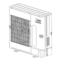
Visual identification and layout of key components in the outdoor unit.
Schematic diagram of the refrigerant circuit and thermal sensor locations for specific models.
Detailed wiring diagram for electrical connections of the outdoor unit.
Key operational data and specifications for cooling mode.
Key operational data and specifications for heating mode.
Configuration settings via DIP switches on the outdoor unit.
Configuration settings via DIP switches on the indoor unit.
Crucial checks and preparations required before initiating a test run.
Explanation of switch functions for registering indoor units with the remote controller.
Step-by-step procedure for registering indoor units into groups.
Overview of control logic and operations for the outdoor unit.
How frequency is controlled for capacity and temperature management.
Logic and conditions governing the defrost operation cycle.
Operation modes for solenoid valves SVA, SVB, and SVC.
Flowchart illustrating the operational logic of the outdoor unit.
Operational flow for the cooling mode of the system.
Relationship between refrigerant amount and system performance.
Methods for adjusting and judging the correct refrigerant amount.
Identification and troubleshooting of principal system parts.
Configuration details and wiring for pressure sensors.
Checking solenoid valve operation against control board signals.
Checking solenoid valve operation against control board signals.
Information regarding the outdoor LEV, including its function and connection.
Steps for removing and installing the SLEV coil.
Details about the check valves block and associated components.
Troubleshooting guide for the Intelligent Power Module (IPM).
Procedure for performing a continuity check on the diode stack.
Common issues with the remote controller and their solutions.
Step-by-step procedure for checking the 30V transmission power circuit.
Methods for analyzing transmission signal quality and identifying noise issues.
Troubleshooting steps for issues related to the fan motor.
Steps to diagnose and resolve issues causing breaker trips.
Methods for diagnosing failures in specific electronic components.
Troubleshooting guide for key components of the BC controller.
Troubleshooting procedure for temperature sensors.
Diagnostic flow for LEV and solenoid valve issues.
Checking LEV full open/closed conditions and basic operation characteristics.
Troubleshooting steps for solenoid valve issues.
Coordination of solenoid valve operations with board signals.
Checking the transformer on the BC controller.
Instructions for disassembling the BC controller for service.
Instructions for removing the service panel of the BC controller.
Procedure for accessing and checking the control box components.
Steps for checking thermistors used for piping temperature detection.
Procedure for removing and installing pressure sensors.
Service procedures for the LEV component.
Steps for removing and replacing solenoid valve coils.
Comprehensive list of error codes and their meanings.
Troubleshooting guide for mechanical issues based on check codes.
Diagnosis and countermeasures for discharge temperature abnormalities.
Troubleshooting steps for low pressure abnormalities in the outdoor unit.
Diagnosis and remedies for suction pressure abnormalities.
Troubleshooting steps for reverse phase power supply issues.
Diagnosing and resolving fan speed abnormalities.
Troubleshooting guide for cooling fan issues.
Troubleshooting for discharge temperature sensor (TH1) issues.
Identifying and resolving multiple address errors in the communication system.
Troubleshooting transmission processor hardware faults.
Diagnosing and resolving transmission circuit bus-busy errors.
Troubleshooting communication errors between processors.
Troubleshooting steps for No ACK errors in the communication system.
Troubleshooting for systems with multiple refrigerants and group operation.
Troubleshooting steps for systems connected via MELANS.
Troubleshooting general system errors.
Diagnosing and correcting address setting errors.
Troubleshooting errors related to incorrect connection numbering.
Resolving errors where the remote controller sensor is not providing designed temperature.
Troubleshooting errors from incompatible indoor model and BC controller connections.
Guide to interpreting LED indicators on the control circuit board for diagnostics.
Explanation of how to read and interpret LED status indicators.
Procedures for preparing, repairing, and refilling refrigerant after leaks.
Procedure for locating refrigerant leaks in piping and indoor units during cooling.
Steps to find refrigerant leaks specifically in the outdoor unit during cooling.
Procedure for locating refrigerant leaks in piping and indoor units during heating.
Steps to find refrigerant leaks specifically in the outdoor unit during heating.
Procedure for checking and calibrating refrigerant composition.