EasyManua.ls Logo

Mitsubishi Electric PUZ-A12NKA7 User Manual

Mitsubishi Electric PUZ-A12NKA7
120 pages
To Next Page IconTo Next Page
Page #1 background imageLoading...
Page #1 background image
1
SERVICE MANUAL
CONTENTS
1. REFERENCE MANUAL ································· 2
2. SAFETY PRECAUTION ································· 2
3. FEATURES ····················································· 7
4. SPECIFICATIONS ·········································· 8
5. DATA ····························································· 10
6. OUTLINES AND DIMENSIONS ··················· 14
7. WIRING DIAGRAM ······································ 17
8. WIRING SPECIFICATIONS ·························· 20
9.
REFRIGERANT SYSTEM DIAGRAM
············· 21
10. TROUBLESHOOTING ·································· 24
11. EASY MAINTENANCE FUNCTION·············· 84
12. FUNCTION SETTING ··································· 87
13.
MONITORING THE OPERATION DATA BY THE REMOTE CONTROLLER
·····95
14. DISASSEMBLY PROCEDURE ··················· 104
R410A
Outdoor unit
[Model Name]
PUZ-A12NKA7
PUZ-A18NKA7
PUZ-A24NHA7
PUZ-A30NHA7
PUZ-A36NKA7
PUZ-A42NKA7
PUZ-A12NKA7-BS
PUZ-A18NKA7-BS
PUZ-A24NHA7-BS
PUZ-A30NHA7-BS
PUZ-A36NKA7-BS
PUZ-A42NKA7-BS
PUY-A12NKA7
PUY-A18NKA7
PUY-A24NHA7
PUY-A30NHA7
PUY-A36NKA7
PUY-A42NKA7
PUY-A12NKA7-BS
PUY-A18NKA7-BS
PUY-A24NHA7-BS
PUY-A30NHA7-BS
PUY-A36NKA7-BS
PUY-A42NKA7-BS
[Service Ref.]
PUZ-A12NKA7
PUZ-A18NKA7
PUZ-A24NHA7
PUZ-A30NHA7
PUZ-A36NKA7
PUZ-A42NKA7
PUZ-A12NKA7-BS
PUZ-A18NKA7-BS
PUZ-A24NHA7-BS
PUZ-A30NHA7-BS
PUZ-A36NKA7-BS
PUZ-A42NKA7-BS
PUY-A12NKA7
PUY-A18NKA7
PUY-A24NHA7
PUY-A30NHA7
PUY-A36NKA7
PUY-A42NKA7
PUY-A12NKA7-BS
PUY-A18NKA7-BS
PUY-A24NHA7-BS
PUY-A30NHA7-BS
PUY-A36NKA7-BS
PUY-A42NKA7-BS
PUZ-A12/18NKA7
PUY-A12/18NKA7
PARTS CATALOG (OCB636)
Notes:
•Thismanualdescribesservice
dataoftheoutdoorunitsonly.
RoHScompliantproductshave
<G> markonthespecname
plate.
SPLIT-TYPE,HEATPUMPAIRCONDITIONERS
SPLIT-TYPE,AIRCONDITIONERS
February 2017
No. OCH636
REVISED EDITION-A
Revision:
CorrectedtheSHFvaluein
"5-4.STANDARDOPERATION
DATA"inREVISEDEDITION-A.
Somedescriptionshavebeen
modified.
OCH636 isvoid.

Other manuals for Mitsubishi Electric PUZ-A12NKA7

Question and Answer IconNeed help?

Do you have a question about the Mitsubishi Electric PUZ-A12NKA7 and is the answer not in the manual?

Mitsubishi Electric PUZ-A12NKA7 Specifications

General IconGeneral
BrandMitsubishi Electric
ModelPUZ-A12NKA7
CategoryAir Conditioner
LanguageEnglish

Summary

1 REFERENCE MANUAL

Indoor Unit Model Specifications

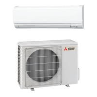
Lists indoor unit models, service references, and manual numbers.

2 SAFETY PRECAUTION

General Safety Guidelines

Essential safety rules for repair and maintenance procedures.

Cautions for New Refrigerant

Precautions for using R410A refrigerant and required tools.

Refrigerant Piping Work Cautions

Guidelines for safe and correct refrigerant piping installation for R410A.

Low Ambient Cooling Precautions

Considerations for operating the unit in low ambient temperatures.

3 FEATURES

Chargeless System Overview

Explanation of the pre-charged refrigerant system and its benefits.

4 SPECIFICATIONS

Refrigerant Charge and Compressor Data

Tables for refrigerant charge amounts and compressor technical specifications.

Noise Criterion Curves

Sound pressure level data presented as noise criterion curves.

Standard Operation Data

Operating parameters and performance data for standard models.

6 OUTLINES AND DIMENSIONS

Unit Dimensions and Installation Requirements

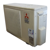
Physical dimensions, installation space, foundation, and piping/wiring details.

7 WIRING DIAGRAM

8 WIRING SPECIFICATIONS

Power Supply and Wiring Details

Specifications for power supply, wiring sizes, and ratings for A-control application.

9 REFRIGERANT SYSTEM DIAGRAM

10 TROUBLESHOOTING

Troubleshooting Steps and Error Codes

Guidance on diagnosing issues, check codes, and general troubleshooting.

Test Run Procedures

Procedures for performing test runs and checking unit operation.

10-3 SELF-DIAGNOSIS

Self-Diagnosis Operation Guide

How to access and perform self-diagnosis using the remote controller.

Remote Controller Diagnosis

Procedure for checking the remote controller's operational status and functionality.

10-4 SELF-DIAGNOSIS ACTION TABLE

Abnormalities on Power On

Troubleshooting table for issues detected upon initial power supply.

Abnormalities During Operation

Troubleshooting table for issues occurring while the unit is running.

10-5 TROUBLESHOOTING OF PROBLEMS

10-6 HOW TO CHECK THE PARTS

Component Resistance Checks

Diagnostic steps and resistance values for checking various unit components.

10-7 HOW TO CHECK THE COMPONENTS

Thermistor Data and Formulas

Detailed resistance values and formulas for checking thermistors.

Linear Expansion Valve Checks

Procedures for checking LEV operation and attachment/detachment.

10-8 EMERGENCY OPERATION

Emergency Operation Cautions and Procedures

Cautions, procedures for starting, and releasing emergency operation.

10-9 TEST POINT DIAGRAM

Power Module Diagnostic Points

Identification of critical test points on the power module for troubleshooting.

10-10 FUNCTION OF SWITCHES, CONNECTORS AND JUMPERS

DIP Switch Functions and Settings

Explanation of DIP switch functions, settings, and effective timing.

Connector Functions

Details on connector functions, particularly CN31 for emergency operation.

Special Functions (Low Noise/Demand Control)

Explanation of special functions like low-noise mode and demand control.

11 EASY MAINTENANCE FUNCTION

Smooth Maintenance Function Guide

How to use the Smooth Maintenance function to view operational data.

11-2 GUIDE FOR OPERATION CONDITION

11-3 INITIAL SETTINGS FOR REFRIGERANT LEAKAGE DETECTION FUNCTION

Refrigerant Leakage Detection Setup

Procedure for initial setup and data reset for leak detection.

12 FUNCTION SETTING

Unit Function Settings via Remote Controller

Guide to setting unit functions using the remote controller.

Wired Remote Controller Function Selection

Steps for selecting functions using the wired remote controller.

IR Wireless Remote Controller Function Selection

Steps for selecting functions using the IR wireless remote controller.

12-2 FUNCTION SELECTION OF REMOTE CONTROLLER

PAR-32MAA Remote Controller Functions

Explanation of the PAR-32MAA remote controller's buttons and screen functions.

12-3 Function selection of IR wireless remote controller

Temperature Display Unit Setting (°C/°F)

How to change the temperature display unit between Celsius and Fahrenheit.

13 MONITORING THE OPERATION DATA BY THE REMOTE CONTROLLER

Operation Data Monitoring Guide

Steps to monitor unit data, thermistor temps, and error history via remote.

Request Code List and Details

Comprehensive list of request codes and their corresponding operational data.

14 DISASSEMBLY PROCEDURE

Removing External Panels and Fan Motor

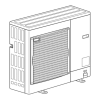
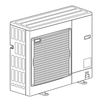
Steps to remove the outdoor unit's outer panels and the fan motor assembly.

Removing Internal Components

Procedures for removing electrical parts, thermistors, coils, valves, switches, reactor, capacitor, compressor, and power receiver.

Related product manuals