SERVICE MANUAL
SPLIT-TYPE, HEAT PUMP AIR CONDITIONERS
SPLIT-TYPE, AIR CONDITIONERS
CONTENTS
1. TECHNICAL CHANGES·································2
2. REFERENCE MANUAL··································2
3. SAFETY PRECAUTION··································3
4. FEATURES ·····················································6
5. SPECIFICATIONS···········································7
6. DATA ·······························································9
7. OUTLINES AND DIMENSIONS····················13
8. WIRING DIAGRAM·······································16
9. WIRING SPECIFICATIONS ··························20
10.
REFRIGERANT SYSTEM DIAGRAM
··············23
11. TROUBLESHOOTING···································26
12. EASY MAINTENANCE FUNCTION··············81
13. FUNCTION SETTING····································84
14.
MONITORING THE OPERATION DATA BY THE REMOTE CONTROLLER
············92
15. DISASSEMBLY PROCEDURE ···················102
16. PARTS LIST ················································117
17. RoHS PARTS LIST ·····································126
No.OC367
REVISED EDITION-C
R410A
June 2007
[model names]
PUZ-A18NHA
PUZ-A24NHA
PUZ-A30NHA
PUZ-A36NHA
PUZ-A42NHA
PUZ-A18NHA-BS
PUZ-A24NHA-BS
PUZ-A30NHA-BS
PUZ-A36NHA-BS
PUZ-A42NHA-BS
PUY-A12NHA
PUY-A18NHA
PUY-A24NHA
PUY-A30NHA
PUY-A36NHA
PUY-A42NHA
PUY-A12NHA-BS
PUY-A18NHA-BS
PUY-A24NHA-BS
PUY-A30NHA-BS
PUY-A36NHA-BS
PUY-A42NHA-BS
[Service Ref.]
PUZ-A18NHA
PUZ-A24NHA
PUZ-A30NHA
PUZ-A36NHA
PUZ-A42NHA
PUZ-A18NHA-BS
PUZ-A24NHA-BS
PUZ-A30NHA-BS
PUZ-A36NHA-BS
PUZ-A42NHA-BS
PUY-A12NHA PUY-A12NHA
1
PUY-A18NHA PUY-A18NHA1
PUY-A24NHA PUY-A24NHA1
PUY-A30NHA PUY-A30NHA1
PUY-A36NHA PUY-A36NHA1
PUY-A42NHA
PUY-A12NHA
1-BS
PUY-A18NHA
1-BS
PUY-A24NHA
1-BS
PUY-A30NHA
1-BS
PUY-A36NHA
1-BS
PUY-A42NHA-BS
NOTE:
• This manual describes only
service data of the outdoor
units.
• RoHS compliant products
have <G> mark on the spec
name plate.
• For servicing RoHS compliant
products, refer to the RoHS
PARTS LIST.
PUZ-A24/30/36NHA
PUY-A24/30/36NHA
Revision:
• “9-2. SEPARATE INDOOR
UNIT/OUTDOOR UNIT
POWER SUPPLIES” is
deleted in REVISED
EDITION-C.
• Some descriptions have
been modified.
• Please void OC367 REVISED
EDITION-B.
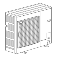
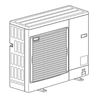
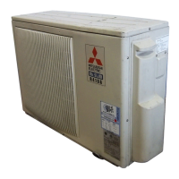
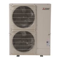
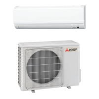
Outdoor unit
OC367C--1.qxp 07.6.20 0:56 PM Page 1