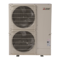
Do you have a question about the Mitsubishi Electric PUZ-A24NHA4 and is the answer not in the manual?
| Heating Capacity | 27, 000 BTU/h |
|---|---|
| Voltage | 208/230V |
| Phase | 1 |
| Refrigerant | R410A |
| Type | Heat Pump |
| Cooling Capacity | 24000 BTU/h |
| SEER | 16.0 |
| HSPF | 9.0 |
| Energy Efficiency Ratio (EER) | 12.0 |
| Energy Efficiency Ratio (Cooling) | 12.0 |
Lists indoor unit models, service references, and manual numbers for reference.
Essential safety rules before accessing terminals and circuits.
Precautions for using R410A refrigerant and related tools.
Specifies pipe thickness and flare nut dimensions for R410A.
Details tools required for R410A refrigerant work and compatibility.
Information on pre-charged refrigerant for piping length at shipment.
Electrical data, compressor model, motor output, RLA, LRA.
Fan details, airflow, sound level, dimensions, and weight.
Refrigerant charge, oil type, pipe sizes, and maximum piping length.
Refilling refrigerant charge amounts for various models and piping lengths.
Technical data for compressors including winding resistance.
Noise levels for different models in cooling and heating modes.
Electrical, refrigerant, and temperature data for heat pump models.
Electrical, refrigerant, and temperature data for cooling-only models.
Overall unit dimensions, minimum installation space, and free space requirements.
Guidelines for foundation bolts and piping/wiring connection directions.
Wiring diagrams for outdoor units, including model select and M-NET adapter.
Wiring specifications for 1:1 and simultaneous twin systems.
Wiring specifications for units with separate power supplies.
Specifications for indoor-outdoor connecting cables, including length and wire size.
Guidelines for M-NET wiring, including noise prevention and grounding.
Procedure for setting M-NET addresses for outdoor units.
Procedure for setting refrigerant addresses for indoor units.
Rules and guidelines for address settings in multi-grouping systems.
System diagrams for PUZ outdoor units showing refrigerant flow.
System diagrams for PUY outdoor units showing refrigerant flow.
Summary of error code display and actions for recurring/non-recurring issues.
Pre-test run checks including wiring, impedance, and power supply.
Steps for performing self-diagnosis during operation and maintenance.
Action table for abnormalities detected when power is on or unit is operating.
Troubleshooting common issues like remote controller display or unit operation.
Resistance values and checks for various electronic components.
Thermistor resistance charts and linear expansion valve checks.
Procedures and cautions for emergency operation mode.
Diagrams showing test points on various circuit boards.
Functions of switches, connectors, and jumpers on control boards.
Setting for reducing outdoor unit operation sound via external signal.
Setting for reducing power consumption via external input.
Interpretation of LED blinking patterns and diagnostic codes for inspection.
How to use SW2 to display various operational data and error codes.
Steps to enter and use maintenance mode for data checking.
Procedure for measuring operation data and setting refrigerant addresses.
Guide for checking operation condition based on temperature differences.
How to set various unit functions using the wired remote controller.
Detailed procedure for selecting functions using a wired remote controller.
Detailed procedure for selecting functions using a wireless remote controller.
How to change temperature display mode from °F to °C.
Steps to access maintenance monitor and request operation data.
List of request codes and their corresponding data descriptions.
Detailed explanations for various request codes and their data displays.
Steps to remove outer panels and the fan motor.
Procedures for removing electrical parts box and various thermistors.
Steps to remove valves, switches, reactor, and capacitor.
Procedures for removing the compressor and accumulator.


 Loading...