1
SERVICE MANUAL
CONTENTS
1. REFERENCE MANUAL ································· 2
2. SAFETY PRECAUTION ································· 2
3. FEATURES ····················································· 7
4. SPECIFICATIONS ·········································· 8
5. DATA ····························································· 10
6. OUTLINES AND DIMENSIONS ··················· 14
7. WIRING DIAGRAM ······································ 17
8. WIRING SPECIFICATIONS ·························· 20
9.
REFRIGERANT SYSTEM DIAGRAM
············· 21
10. TROUBLESHOOTING ·································· 24
11. EASY MAINTENANCE FUNCTION·············· 84
12. FUNCTION SETTING ··································· 87
13.
MONITORING THE OPERATION DATA BY THE REMOTE CONTROLLER
·····95
14. DISASSEMBLY PROCEDURE ··················· 104
R410A
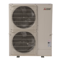
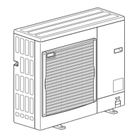
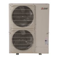
Outdoor unit
[Model Name]
PUZ-A12NKA7
PUZ-A18NKA7
PUZ-A24NHA7
PUZ-A30NHA7
PUZ-A36NKA7
PUZ-A42NKA7
PUZ-A12NKA7-BS
PUZ-A18NKA7-BS
PUZ-A24NHA7-BS
PUZ-A30NHA7-BS
PUZ-A36NKA7-BS
PUZ-A42NKA7-BS
PUY-A12NKA7
PUY-A18NKA7
PUY-A24NHA7
PUY-A30NHA7
PUY-A36NKA7
PUY-A42NKA7
PUY-A12NKA7-BS
PUY-A18NKA7-BS
PUY-A24NHA7-BS
PUY-A30NHA7-BS
PUY-A36NKA7-BS
PUY-A42NKA7-BS
[Service Ref.]
PUZ-A12NKA7
PUZ-A18NKA7
PUZ-A24NHA7
PUZ-A30NHA7
PUZ-A36NKA7
PUZ-A42NKA7
PUZ-A12NKA7-BS
PUZ-A18NKA7-BS
PUZ-A24NHA7-BS
PUZ-A30NHA7-BS
PUZ-A36NKA7-BS
PUZ-A42NKA7-BS
PUY-A12NKA7
PUY-A18NKA7
PUY-A24NHA7
PUY-A30NHA7
PUY-A36NKA7
PUY-A42NKA7
PUY-A12NKA7-BS
PUY-A18NKA7-BS
PUY-A24NHA7-BS
PUY-A30NHA7-BS
PUY-A36NKA7-BS
PUY-A42NKA7-BS
PUZ-A12/18NKA7
PUY-A12/18NKA7
PARTS CATALOG (OCB636)
Notes:
•Thismanualdescribesservice
dataoftheoutdoorunitsonly.
•
RoHScompliantproductshave
<G> markonthespecname
plate.
SPLIT-TYPE,HEATPUMPAIRCONDITIONERS
SPLIT-TYPE,AIRCONDITIONERS
February 2017
No. OCH636
REVISED EDITION-A
Revision:
•
CorrectedtheSHFvaluein
"5-4.STANDARDOPERATION
DATA"inREVISEDEDITION-A.
• Somedescriptionshavebeen
modified.
• OCH636 isvoid.