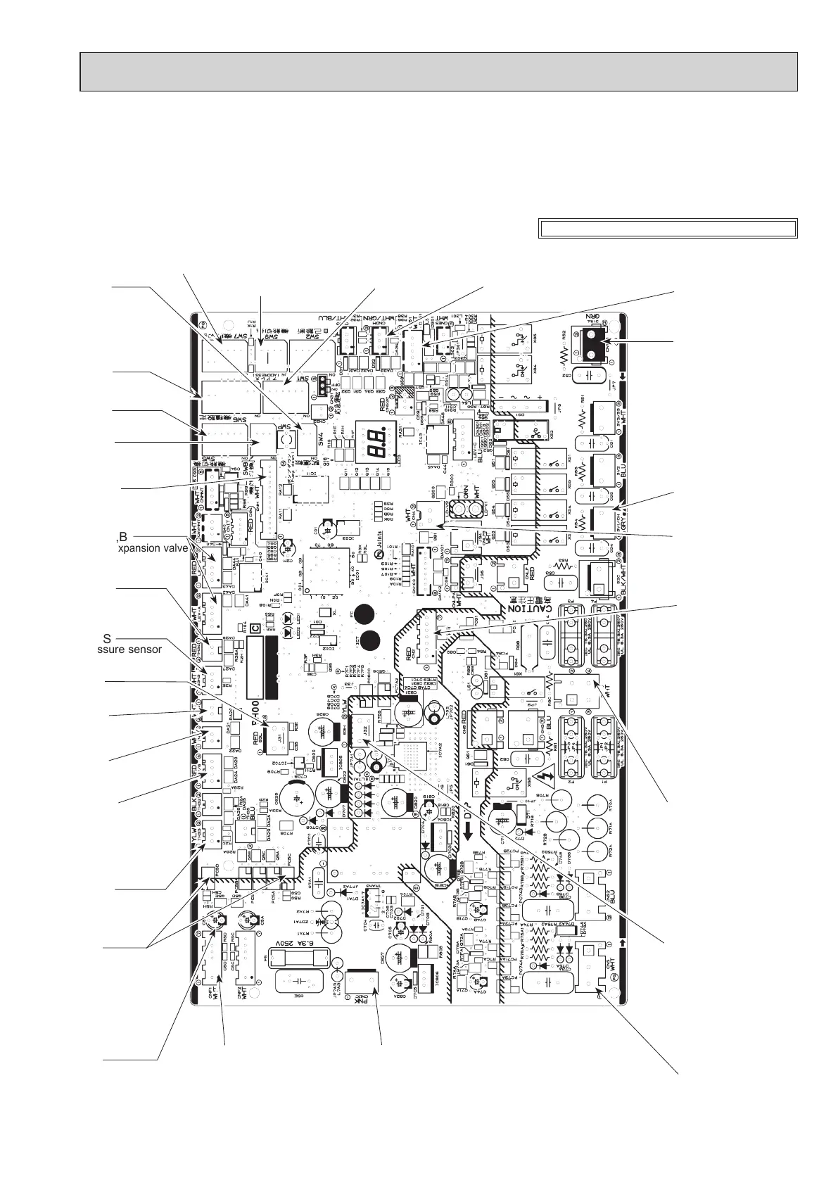
43
OCH727
CNS
S1-S2: 230 V AC
CNAC
2–4:
Power supply for outdoor
noise filter circuit board
(230 V AC)
1–3:
Power supply for indoor
and outdoor unit connection
wire (230 V AC)
CNF1
Connect to the fan motor
1–4: 280–380V DC
5–4: 15 V DC
6–4: 0–6.5V DC
7–4: 15 V DC (When stopped)
7.5 V DC (When operated)
(0–15 V pulse)
21S4
4-way valve
63H
High pressure
switch
CN4
Transmission to out-
door power circuit
board (CN4)
SW4
Function switch
SW6
Model select
SW5
Function switch
SW1
Manual defrost, defect
history record reset,
refrigerant address
CNDM
1–2:
Input of low-level sound priority mode
1–3:
Input of external contact point
CNDC
280–380 V DC (1+, 3−)
(Outdoor power circuit board for W60VAA, W85VAA,112VAA)
(Noise filter circuit board for W85YAA,112YAA)
SW7
Function switch
CN51
External signal output
• Compressor operat-
ing signal
• Abnormal signal
LEV-A,B
Linear expansion valve
SW8
Function switch
CNM
Connect to A control
service tool
CN2
Connect to the outdoor
power circuit board (CN2)
1–5: Reception from
power circuit board
2–5: Zero cross signal
(0–5 V DC)
3–4: Not used
(W85Y, W112Y)
18 V DC
(W60V, W85V,
W112V)
6–5: 16 V DC
7–5: 16 V DC
9-6. TEST POINT DIAGRAM
Outdoor controller circuit board
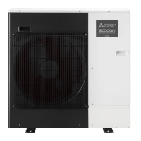
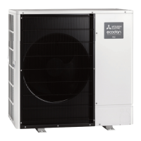
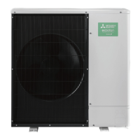
PUZ-WM50VHA.UK PUZ-WM60VAA.UK PUZ-WM85VAA.UK
PUZ-WM50VHA-BS.UK PUZ-WM60VAA-BS.UK PUZ-WM85VAA-BS.UK
PUZ-WM85YAA.UK PUZ-WM112VAA.UK PUZ-WM112YAA.UK
PUZ-WM85YAA-BS.UK PUZ-WM112VAA-BS.UK PUZ-WM112YAA-BS.UK
SV1
Drain hose heater output
SW9
Function switch
<CAUTION> TEST POINT1 is high voltage.
TH4
Thermistor
<Discharge>
TH3
Thermistor
<Liquid>
TH7/6
Thermistor
<Ambient/
2-phase pipe>
63L
Low pressure switch
63HS
Pressure sensor
TH33
Thermistor
<Comp. Surface>
VFG
(Voltage between
right pins of PC5C
and PC5D, pin 3
and pin 4)
(Same as
(CNF17(+)–4(−))
VSP
(Voltage between pins
of C5B):
0 V DC(when stopped),
1–6.5 V DC
(when operated)
TH34
Thermistor
<Plate hex liquid>
 Loading...