EasyManua.ls Logo

Mitsubishi Electric PUZ-WM85VAA-BS.UK User Manual

Mitsubishi Electric PUZ-WM85VAA-BS.UK
86 pages
To Next Page IconTo Next Page
Page #1 background imageLoading...
Page #1 background image
SERVICE MANUAL
No. OCH727
R32
March 2020
PARTS CATALOG (OCB727)
<Outdoor unit>
[Model Name]
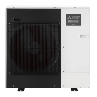
PUZ-WM50VHA
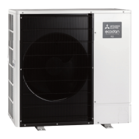
PUZ-WM60VAA
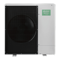
PUZ-WM85VAA
PUZ-WM85YAA
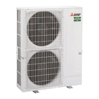
PUZ-WM112VAA
PUZ-WM112YAA
Salt proof model
PUZ-WM50VHA-BS
PUZ-WM60VAA-BS
PUZ-WM85VAA-BS
PUZ-WM85YAA-BS
PUZ-WM112VAA-BS
PUZ-WM112YAA-BS
CONTENTS
1. REFERENCE MANUAL ································ 2
2. SAFETY PRECAUTION ······························· 3
3. SPECIFICATIONS ······································ 10
4. DATA ··························································· 12
5. OUTLINES AND DIMENSIONS·················· 13
6. WIRING DIAGRAM ····································· 15
7. WIRING SPECIFICATIONS ························ 18
8. REFRIGERANT SYSTEM DIAGRAM ········ 19
9. TROUBLESHOOTING ································ 22
10.
MONITORING THE OPERATION DATA BY THE REMOTE CONTROLLER
···· 60
11. DISASSEMBLY PROCEDURE ··················· 66
Note:
• This manual describes
service data of the outdoor
units only.
AIR TO WATER HEAT PUMP UNITS
[Service Ref.]
PUZ-WM50VHA.UK
PUZ-WM60VAA.UK
PUZ-WM85VAA.UK
PUZ-WM85YAA.UK
PUZ-WM112VAA.UK
PUZ-WM112YAA.UK
PUZ-WM50VHA-BS.UK
PUZ-WM60VAA-BS.UK
PUZ-WM85VAA-BS.UK
PUZ-WM85YAA-BS.UK
PUZ-WM112VAA-BS.UK
PUZ-WM112YAA-BS.UK
PUZ-WM50VHA.UK

Table of Contents

Question and Answer IconNeed help?

Do you have a question about the Mitsubishi Electric PUZ-WM85VAA-BS.UK and is the answer not in the manual?

Mitsubishi Electric PUZ-WM85VAA-BS.UK Specifications

General IconGeneral
ModelPUZ-WM85VAA-BS.UK
CategoryHeat Pump
Heating Capacity8.5 kW
Cooling Capacity8.0 kW
Energy Efficiency RatingA++
RefrigerantR32
Power Supply230V, 50Hz
Operating Temperature Range (Cooling)-5°C to 46°C
TypeAir Source Heat Pump
Operating Temperature Range (Heating)-20°C to 24°C

Summary

Safety Precaution

2-2. Cautions Related to New Refrigerant

Specific precautions for using R32 refrigerant.

1. Warning for Service

Detailed warnings and precautions for service personnel.

4. Cautions for Unit Using R32 Refrigerant

Detailed safety guidelines for units using R32 refrigerant.

Specifications

Wiring Diagram

Wiring Specifications

Refrigerant System Diagram

Troubleshooting

9-1. Troubleshooting

Overview of self-diagnosis and troubleshooting actions.

9-2. Self-Diagnosis Action Table

Table correlating check codes with causes and actions.

9-3. Troubleshooting of Problems

Guide to resolving common operational problems and phenomena.

9-4. How to Check the Parts

Procedures for testing and checking various unit components.

9-5. How to Check the Components

Detailed methods for checking specific components like sensors and valves.

9-6. Test Point Diagram

Diagrams showing test points on circuit boards for diagnosis.

9-7. Function of Switches, Connectors and Jumpers

Explanation of DIP switch functions and connector pinouts.

Disassembly Procedure

Related product manuals