18
OCH727
7
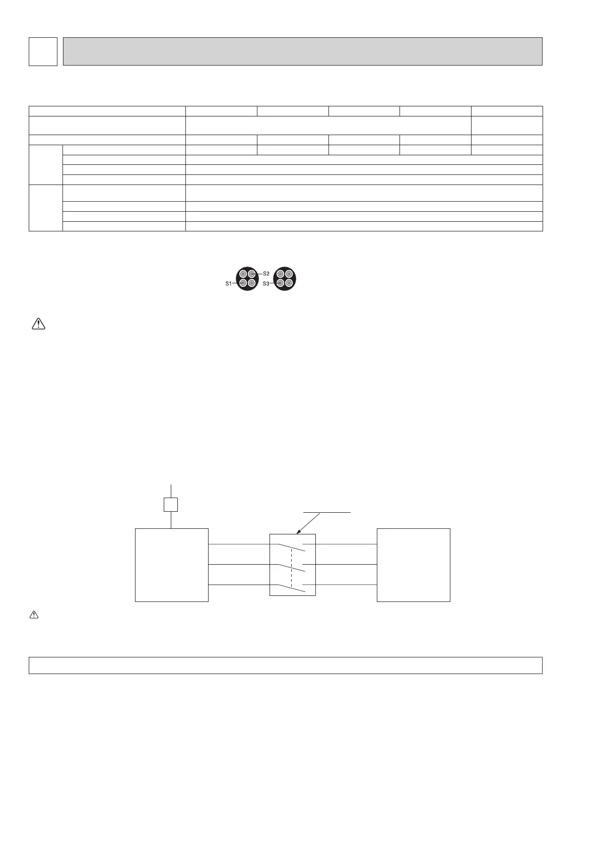
WIRING SPECIFICATIONS
FIELD ELECTRICAL WIRING (power wiring specifications)
Outdoor unit model
WM50V WM60V WM85V WM112V WM85Y, WM112Y
Outdoor unit power supply
~/N (single), 50 Hz, 230 V
3N~ (3 ph 4-wires),
50 Hz, 400 V
Outdoor unit input capacity Main switch (Breaker) *1
16 A 16 A 25 A 32 A 16 A
Wiring Wire
No. × size
(mm2)
Outdoor unit power supply
3 × Min 1.5 3 × Min 2.5 3 × Min 2.5 3 × Min 4 5 × Min 1.5
Indoor unit-Outdoor unit *2
3 × 1.5 (polar)
Indoor unit-Outdoor unit earth *2
1 × Min 1.5
Remote controller-Indoor unit
2 ×0.3 (Non-polar)
Circuit rating
"Outdoor unit L-N (single)
Outdoor unit L1-N, L2-N, L3-N (3 phase)"
*3
230 V AC
Indoor unit-Outdoor unit S1-S2 *3
230 V AC
Indoor unit-Outdoor unit S2-S3 *3
24 V DC
Remote controller-Indoor unit *3
12 V DC
*1. A breaker with at least 3.0 mm contact separation in each pole shall be provided. Use earth leakage breaker (NV).
Make sure that the current leakage breaker is one compatible with higher harmonics.
Always use a current leakage breaker that is compatible with higher harmonics as this unit is equipped with an inverter.
The use of an inadequate breaker can cause the incorrect operation of inverter.
*2.Maximum 45 m
If 2.5 mm² is used, maximum 50 m.
If 2.5 mm² is used and S3 is separated, maximum 80 m.
*3. The gures are NOT always against the ground.
S3 terminal has 24 V DC against S2 terminal. However between S3 and S1, these terminals are NOT electrically insulated by the transformer or other device.
S1
S2
S3
S1
S2
S3
Warning:
· In case of A-control wiring, there is high voltage potential on the S3 terminal caused by electrical circuit design that has no electrical insulation
between power line and communication signal line. Therefore, please turn off the main power supply when servicing. And do not touch the S1, S2, S3
terminals when the power is energized. If isolator should be used between indoor unit and outdoor unit, please use 3-pole type.
Caution: Be sure to install N-line. Without N-line, it could cause damage to the unit.
Notes: 1. Wiring size must comply with the applicable local and national codes.
2.
Power supply cables and the cables between Interface unit/Flow temp. controller and outdoor unit shall not be lighter than polychloroprene
sheathed exible cables. (Design 60245 IEC 57
)
3. Be sure to connect the cables between
Interface unit/Flow temp. controller
and outdoor unit directly to the units (no intermediate connections
are allowed).
Intermediate connections may result in communication errors. If water enters at the intermediate connection point, it may cause insufcient
insulation to ground or a poor electrical contact.
(If an intermediate connection is necessary, be sure to take measures to prevent water from entering the cables.)
4. Install an earth line longer than power cables.
5. Do not construct a system with a power supply that is turned ON and OFF frequently.
6. Use self-extinguishing distribution cable for power supply wiring.
7. Properly route wiring so as not to contact the sheet metal edge or screw tip.
Outdoor Unit
3 poles isolator
Power
supply
Isolator
Indoor unit
(Interface unit /
Flow temp.
controller)
Never splice the power cable or the Interface unit/Flow temp. controller-outdoor unit connection cable, otherwise it may result in smoke emission, a re or communi-
cation failure.
 Loading...