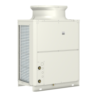
1. Product Specifications
3. Flow sensor wiring connection
4. Cautionary notes
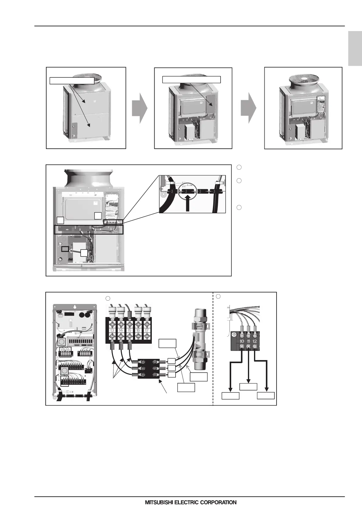
(1) Open the panel.
Using a screwdriver, remove the SERVICE PANEL and the CONTROL BOX (SUB) cover.
(2) Thread the wiring into the unit.
C
A
B
Thread the flow sensor wiring through A in the
Hold the wiring with the cable strap inside
it out of contact with the pipes and other
components.
Thread the wiring through the rubber bush
the left).
* Refer to the Installation/Operation Manual of QAHV-
N136TAU-HPB for the detailed explanation on how
to open the part indicated as A and how to route the
wiring indicated as B in the figure.
* Perform wiring work for the flow output adjustment
device and the thermistor at the same time.
(3) Connect the wiring.
13
14
15
0-10V
+10V
GND
Connect the flow sensor
wiring to the terminal block
inside the BOX. The numbers
on the wirings correspond to
the numbers on the terminal
block.
Connect each wiring to the
correct terminal.
When done, hold the excess
wiring with the supplied cable
tie (long).
Also, hold the wirings in
place with a cable tie (long)
where indicated as B in the
contact with the pipes and
other components.
(4) Close the panel.
Using a screwdriver, re-place the SERVICE PANEL and the CONTROL BOX (SUB) cover.
CONTROL BOX (SUB)
SERVICE PANEL
Flow sensorTerminal block box
Black
Wiring
(not supplied)
Terminal block
(not supplied)
White
Red
Flow adjusting device
(Reference)
figure.
the unit indicated as B in the figure to keep
indicated as C in the figure (second one from
figure to keep them out of
1
2
3
2
1
1
2
 Loading...