EasyManua.ls Logo

Mitsubishi Electric TRANE NTXCKS12A112AA User Manual

Mitsubishi Electric TRANE NTXCKS12A112AA
36 pages
To Next Page IconTo Next Page
Page #1 background imageLoading...
Page #1 background image
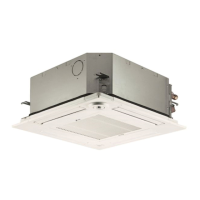
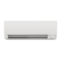
Indoor unit
[Model Name]
NTXCKS09A112AA
NTXCKS12A112AA
NTXCKS15A112AA
NTXCKS18A112AA
TECHNICAL & SERVICE MANUAL
No. OCHT669
CONTENTS
1. REFERENCE MANUAL
......................
2
2. SAFETY PRECAUTION ......................2
3. PARTS NAMES AND FUNCTIONS
.....
4
4. SPECIFICATIONS
...............................
9
5. OUTLINES AND DIMENSIONS
.........
11
6. WIRING DIAGRAM
............................
13
7.
REFRIGERANT SYSTEM DIAGRAM
.....
14
8. TROUBLESHOOTING
.......................
15
9. SPECIAL FUNCTION
........................
28
10. 4-WAY AIRFLOW SYSTEM
...............
30
11. DISASSEMBLY PROCEDURE
..........
32
INDOOR UNIT
Model name
indication
WIRED REMOTE CONTROLLER
(Option)
PARTS CATALOG (OCBT669)
WIRELESS REMOTE
CONTROLLER
(Option)
November 2018

Questions and Answers:

Mitsubishi Electric TRANE NTXCKS12A112AA Specifications

General IconGeneral
CategoryAir Conditioner
BrandMitsubishi Electric TRANE
ModelNTXCKS12A112AA
RefrigerantR410A
Cooling Capacity12000 BTU/h
Heating Seasonal Performance Factor (HSPF)10.0
Power Supply208/230V, 1Ph, 60Hz
Operating Temperature (Cooling)115°F
Operating Temperature (Heating)75°F
Outdoor Unit Dimensions (H x W x D)31.5

Summary

Manual Introduction and Safety Guidelines

R410A Refrigerant Safety and Handling

Details essential safety measures, tool requirements, and handling procedures for R410A refrigerant systems.

Component Identification and Controller Operations

Indoor Unit Parts Identification

Identifies and describes the components of the indoor unit, including air outlets, filters, and grilles.

Technical Specifications and Noise Characteristics

Refrigerant System and Troubleshooting Guide

Refrigerant System Diagram

Diagram showing the refrigerant flow path and key components within the system.

Troubleshooting Summary by Check Code

Summarizes actions for recurring and non-recurring troubles based on self-diagnosis check codes.

Remote Controller Malfunction Diagnosis

Details the self-check procedure using the remote controller to diagnose malfunctions.

Indoor Unit Self-Diagnosis Actions

Provides a table linking check codes to causes and countermeasures for indoor unit abnormalities.

Troubleshooting LED Indicators and Problems

Lists common phenomena related to indoor controller board LEDs and their corresponding causes and countermeasures.

Component Testing, Configuration, and Troubleshooting

Main Parts Troubleshooting and Thermistor Data

Details troubleshooting for main parts, including thermistor characteristics and DC fan motor checks.

Disassembly and Component Removal Procedures

Related product manuals