MODEL: WD-57831 / WD-65831 / WD-73831
Page 5
INTRODUCTION
This service manual provides service instructions for the V33Y and V33+ chassis type. The specfic models for each
chassis type, dimensions and weight are listed below. Service personnel should read this manual thoroughly before
servicing these chassis.
This service manual includes:
1. Assembly and disassembly instructions for cabinet and chassis components.
2. Servicing of the Lenticular Screen and Fresnel Lens.
3. Servicing printed circuit boards (PCBs).
4. Electrical and Mechanical adjustments.
6. Chip parts replacement procedures.
7. Circuit path diagrams.
The parts list section of this service manual includes:
1. Cabinet and screen parts.
2. Electrical parts.
Schematic and block diagrams of the above listed models are included in this service manual for better understanding
of the circuitry.
PRODUCT SAFETY NOTICE
Many electrical and mechanical parts in television receivers have special safety related characteristics. These charac-
teristics are often not evident from visual inspection nor can the protection afforded by them necessarily be obtained by
using replacement components rated for higher voltage, wattage, etc.
Replacement parts which have special safety characteristics are identified in this service manual.
Electrical components having such features are identified by shading on the schematic diagram and parts list of this
service manual, and by marking on the supplementary sheet for this chassis to be issued subsequently. Therefore,
the replacement for any safety part should be identical in value and characteristics.
Pb Solder
The PWBs used in the V34 chassis are constructed using Lead-Free solder. When servicing use
only recommended Lead-Free solder (refer to page 39).
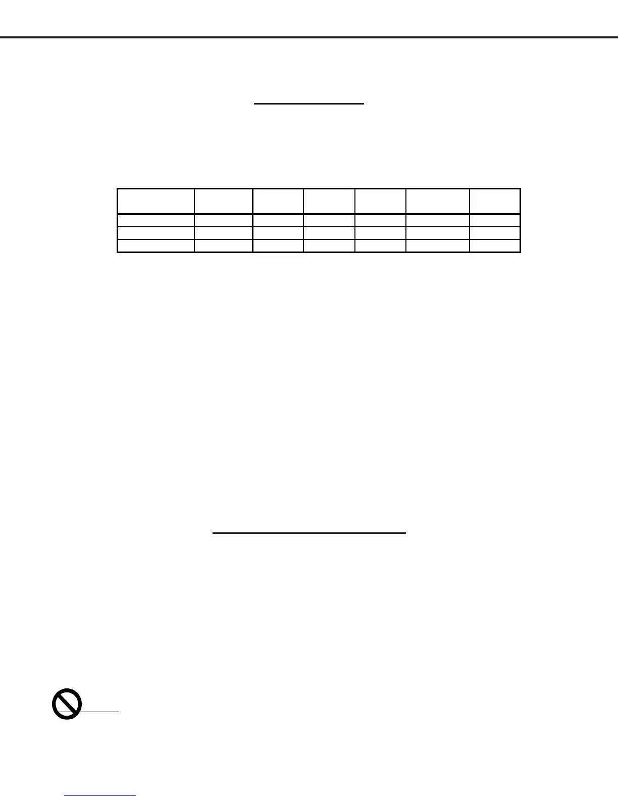
V34 Chassis
MODEL CHASSIS HEIGHT WIDTH DEPTH WEIGHT
POWER
USAGE
WD-57831
V34 36.3" 51.5" 18" 96 lbs 250W
WD-65831
" 40.8" 58.5" 19.8" 103.7 lbs 250W
WD-73831
" 44.8" 70.3 21.5 204lbs 250W
 Loading...