-
93
-
'13 • SRK-T-147
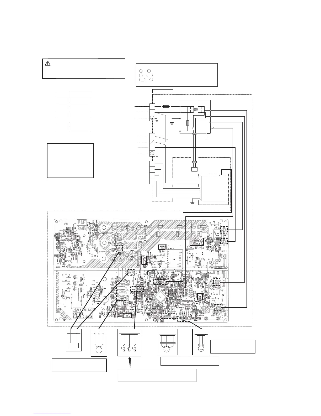
(12) Outdoor unit inspection points
Models SRC63ZMA-S, 71ZMA-S, 80ZMA-S
CAUTION
-
HIGH VOLTAGE
PCB ASSY (MAIN)
High voltage is produced in the control box. Don't touch
electrical part s in the control box for 5 minutes after the
unit is stopped.
◆Inspection of electronic
expansion valve
See page 95.
◆Inspection of resistance valve of sensor
Remove the connector and check the resistance valve.
See the section of sensor characteristics on page 85.
◆Power source and serial signal inspection
L to N : AC 220/230/240V
1 to 2/N : AC 220/230/240V
2/N to 3 : Normal if the voltage oscillates between
DC 0 and approx. 20V
◆Inspection power transistor
Remove the fasten terminal and test
output voltage
◆Inspection of outdoor fan motor
See page 95.
◆Check point of outdoor unit
Color
Color symbol
OR
Mark
BrownBR
Yellow/GreenY/G
BlackBK
BlueBL
WhiteWH
RedRD
Orange
Display Voltage range
◆Voltage check in PCB
The normal range is as follows.
①DC280V DC230V - DC310V
②DC220V DC218V - DC222V
③DC213V DC212V - DC214V
④DC215V DC214V - DC216V
⑤DC225V DC224V - DC226V
⑥DC 2.5V DC 2.3V - DC
2
2.5V
M
T2
(BK)
(WH)
(RD)
V WU
M
CNTH
CNEEV
CNFAN
1 2 3 4 6
t゜
R
(OR)
T1(YE)
2 2 2
TH1 TH2 TH3
EEV
FMo
t゜
t゜
MS
CM
3~
(WH)
(OR)
(BR)
(RD)
(BL)
(BK)
(WH)
(WH)
(BK)
(WH)
(WH)
(BK)
(BK)
(BK)
(BK)
(RD)
4
Power source
1 Phase
AC220-240V 50Hz
Indoor
unit
Outdoor unit
R
S
①
②
④
⑤
⑥
S-2
C-2
③
)BUS(YSSABWP
S‑1
CNMAIN
S
R
R
(BK)
(W H )
G1
(Y/G )
(BR)
IN
IN
OUT
S
R
O
O
N
L
250V20A
FUSE
2
1
N
3
(Y/G )
(Y/G )
CN20S
20S
TB1
TB2
TERMINAL
BLOCK
BLOCK
TERMINAL
(W H )
(Y/G )
G3
D1
D3
D2
C
TB3
BLOCK
TERMINAL
(YE)
(RD )
(BL)
(BK)
(Y/G )
250V10A
F10
(W H )
(BK)
PWBASS Y(DRE D )
CNPOWER
CNDRED
CNDRM
(RD )
(BK)
(RD)
 Loading...