after elapsing 3 minutes
from power OFF
connectors are not half
inserted
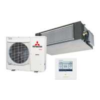
Parts Arrangement View
Fig.1 Position of terminal
CNQ1
CNQ2
SW4
CNEEV1
CNI3
CNW2
Voltage measurement point
(T26(red)ޔT27(blue))
CNTH
Parts No.
CNI1
CNIP
CNB
CNG1
CNA1
CNW
CNH
CNR
CNS
CNN
CNFAN
CNEEV2
CNPS
CNA2
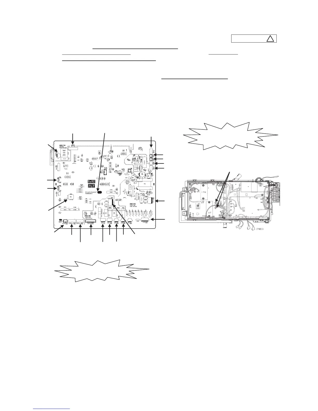
1) Model FDC71VNX
a) Replace the PCB after elapsing 3 minutes from power OFF.
(Be sure to measure voltage (DC) between T26 and T27 on inverter PCB, and check that the
voltage is discharged sufficiently(10V or less).(Refer to Fig.1))
b) Disconnect the connectors from the control PCB.
c) Match the switches setting (SW4) with the former PCB.
d) Connect the connectors to the control PCB.(Confirm the connectors are not half inserted.)
 Loading...