Do you have a question about the Mitsubishi Heavy Industries RC-EX3A and is the answer not in the manual?
| Type | Remote Control |
|---|---|
| Brand | Mitsubishi Heavy Industries |
| Model | RC-EX3A |
| Category | Remote Control |
| Compatible Devices | Mitsubishi Heavy Industries Air Conditioners |
| Display | Yes |
| Display Type | LCD |
| Battery Type | AAA |
| Number of Batteries | 2 |
| Compatibility | Air Conditioners |
| Features | Backlight, Timer Function |
| Functions | Mode selection, Temperature setting, Fan speed adjustment, Timer setting |
Read the precautions carefully to operate the unit properly. Observe all instructions for safety.
Proper disposal of electrical and electronic equipment (WEEE) according to regulations.
Details on product dimensions, weight, power supply, consumption, environment, and material.
Description of the Liquid Crystal Display, its backlight, and automatic turn-off.
Button to start and stop the unit operation.
Switch to start operation set in F1/F2 function setting.
Switch to start operation set in F1/F2 function setting.
Indicator light showing operation status (green for normal, red for error).
Connector for connecting to a personal computer for remote control utility software.
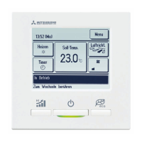
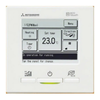
Displays current time and assigned room name.
Shows icons for various settings like demand control, ventilation, and timer.
Access to menu items for setting and changing operations.
Button to select and change the unit's operation mode.
Button to select and change the desired temperature.
Button to select and change the flap direction.
Button to select and change the fan speed.
Button to display and set timer functions.
Button to select the display language for the remote control.
Area for displaying status and messages of the unit and operations.
Shows the function assigned to the F1 and F2 switches.
Core operations like Run, Stop, changing mode, temperature, flap, and fan speed.
Features like flap control, timers, favorite settings, and ventilation.
Settings related to energy conservation, including sleep and peak-cut timers.
Personalization options such as clock, contrast, and administrator settings.
Settings related to installation, IU configuration, and maintenance.
Information for contacting the manufacturer or dealer.
Starts the air conditioner operation. The operation lamp lights green.
Stops the air conditioner operation. The operation lamp turns off.
Select and change the unit's operating mode (Cooling, Fan, Dry, Heating, Auto).
Select and change the desired temperature setting for the unit.
Select and change the direction of the air flow flaps.
Select and adjust the fan speed for the air conditioner.
Using F1/F2 switches as shortcuts for frequently used functions.
Enable or disable the anti-draft function for specific operation modes.
Temporarily increases capacity for rapid temperature adjustment.
Reduces energy consumption by optimizing capacity based on outdoor temp.
Overview of menu items and their corresponding page numbers for quick access.
Details which settings cannot be made on a secondary remote control.
Instructions on navigating through menu screens using Next, Previous, and Back buttons.
Important notes and warnings for various setting screens and operations.
Controls for energy saving features like sleep and peak-cut timers.
Automatically stops operation after a set time has elapsed.
Sets times for capacity limiting operation and peak-cut percentage.
Returns to set temperature after a specified time has counted up.
Detects presence to control power and auto-off features.
Sets the motion range (limit positions) for flaps at each blow outlet.
Enables/disables anti-draft function and panel motion for each blow outlet.
Turns ventilation on or off if a ventilation device is installed.
Basic setup options including clock, date, contrast, and backlight.
Sets and corrects the current date and time for the unit.
Configures the display of date and time, including format and AM/PM position.
Adjusts the current time by one hour for daylight saving.
Adjusts the contrast of the LCD screen for better readability.
Turns the LCD backlight ON/OFF and sets the lighting period.
Enables or disables the audible sound feedback for touch panel operations.
Adjusts the brightness level of the operation indicator lamp.
Accesses various timer settings like ON/OFF by hour/clock and weekly timers.
Sets the unit to start operation after a specified number of hours.
Sets the unit to stop operation after a specified number of hours.
Sets the unit to start operation at a specific clock time.
Sets the unit to stop operation at a specific clock time.
Displays the current timer settings for confirmation.
Sets ON/OFF timer operations for each day of the week.
Maintains moderate room temperature when the unit is not in use.
Saves current operation mode, temp, fan, and flap settings as favorites.
Starts operation using previously saved favorite settings.
Access to advanced settings like permission/prohibition and password changes.
Allows or restricts specific operations and settings.
Sets periods to operate the outdoor unit prioritizing quietness.
Restricts the settable temperature range for cooling or heating.
Changes the temperature increment for set temp adjustments (1.0°C or 0.5°C).
Configures how the set temperature is displayed on the TOP screen.
Customizes information displayed on the remote control screen.
Sets a custom name to be displayed for the room on the TOP screen.
Assigns a name to the Indoor Unit (IU) for easy identification.
Turns the display of indoor room temperature ON or OFF.
Enables or disables the display of error codes on the TOP screen.
Shows a message during heating standby to prevent cold air blowing.
Shows a message when the unit is in defrost operation.
Displays messages for Auto Cooling or Auto Heating mode.
Enables or disables display of various temperature readings.
Allows the administrator password to be changed.
Assigns specific functions to the F1 and F2 switches for quick access.
Controls the unit to prioritize quietness by reducing fan speed or capacity.
Sets the display language for the remote control interface.
Resets the filter cleaning indicator after maintenance.
Instructions on cleaning the remote control's LCD and main body.
Information on contacting support and interpreting error codes.
Message indicating a delay due to cooling machine oil protection.
Indicates the unit is performing a defrost cycle.
Shows unit is ready to blow warm air after preventing cold air.
Indicates the unit is pre-heating the room before the set start time.
Indicates rotation, capacity back-up, or fault back-up operation is active.
Unit controlled by central device; operations outside allowed list are invalid.
Indicates unit is in temporary stop mode due to external input.
Details to provide when contacting the dealer for service or information.
Consult dealer for special technology required for unit relocation.
Information on seeking paid repairs and warranty period details.
Contact dealer or service contact for inquiries about after-sale service.