Dented part
under the panel
To change setting
1. Remove four screws located on the back of the receiver and
detach the board.
2. Change the setting by the switch on PCB.
3. When SW1 is turned to OFF position, change the wireless remote controller setting.
For the method of changing the setting, refer to Setting to avoid mixed communication of
4
Wireless remote controller
.
*The receivable area of the signal refer to
5
Receiver
.
Connect the attached wiring to the signal terminal block primary side XY (for grill side) in the control box,
and connect to the CNL connector (3P white) from the receiver .
This installation is unnecessary for indoor unit that have wiring is already connected from the signal
terminal block to the receiver.
1
234
Default settings
ON
OFF
Switch
WARNING
WARNING
WIRELESS REMOTE
CONTROLLER&RECEIVER
INSTALLATION MANUAL
201701
Safety precautions
1
Accessories
Ɣ
Please read this manual carefully before starting installation work to install the unit properly.
Every one of the followings is important information to be observed strictly.
WARNING Failure to follow these instructions properly may result in serious consequences
such as death, severe injury, etc.
CAUTION Failure to follow these instructions properly may cause injury or property damage.
It could have serious consequences depending on the circumstances.
Ɣ
The following pictograms are used in the text.
Never do.
Always follow the instructions given.
Ɣ
Keep this manual at a safe place where you can consult with whenever necessary. Show this manual to installers when
moving or repairing the unit. When the ownership of the unit is transferred, this manual should be given to a new owner.
Ɣ
Consult your dealer or a professional contractor to install the unit.
Improper installation made on your own may cause electric shocks, fire or dropping of the unit.
Ɣ
Installation work should be performed properly according to this installation manual.
Improper installation work may result in electric shocks, fire or break-down.
Ɣ
Be sure to use accessories and specified parts for installation work.
Use of unspecified parts may result in drop, fire or electric shocks.
Ɣ
Install the unit properly to a place with sufficient strength to hold the weight.
If the place is not strong enough, the unit may drop and cause injury.
Ɣ
Be sure to have the electrical wiring work done by qualified electrical installer, and use exclusive circuit.
Power source with insufficient and improper work can cause electric shock and fire.
Ɣ
Shut OFF the main power supply before starting electrical work.
Otherwise, it could result in electric shocks, break-down or malfunction.
Ɣ
Do not modify the unit.
It could cause electric shocks, fire, or break-down.
Ɣ
Be sure to turn OFF the power circuit breaker before repairing/inspecting the unit.
Repairing/inspecting the unit with the power circuit breaker turned ON could cause electric shocks or
injury.
Ɣ
Do not install the unit in appropriate environment or where inflammable gas could
generate, flow in, accumulate or leak.
If the unit is used at places where air contains dense oil mist, steam, organic solvent vapor, corrosive gas (ammonium,
sulfuric compound, acid, etc) or where acidic or alkaline solution, special spray, etc. are used, it could cause electric
shocks, break-down, smoke or fire as a result of significant deterioration of its performance or corrosion.
Ɣ
Do not install the unit where water vapor is generated excessively or condensation occurs.
It could cause electric shocks, fire, or break-down.
Ɣ
Do not use the unit in a place where it gets wet, such as laundry room.
It could cause electric shocks, fire, or break-down.
Ɣ
Do not operate the unit with wet hands.
It could cause electric shocks.
Ɣ
Do not wash the unit with water.
It could cause electric shocks, fire, or break-down.
Ɣ
Use the specified cables for wiring, and connect them securely with care to protect
electronic parts from external forces.
Improper connections or fixing could cause heat generation, fire, etc.
Ɣ
When installing the unit at a hospital, telecommunication facility, etc., take
measures to suppress electric noises.
It could cause malfunction or break-down due to hazardous effects on the inverter, private
power generator, high frequency medical equipment, radio communication equipment, etc.
The influences transmitted from the remote control to medical or communication equipment
could disrupt medical activities, video broadcasting or cause noise interference.
Ɣ
Do not leave the remote control with its PCB case removed.
If dew, water, insect, etc. enters through the hole, it could cause electric shocks, fire or break-
down.
CAUTION
Please make sure that you have all of the following accessories.
2
Preparation before installation (continued)
4
How to connect the wiring for control box
2
Preparation before installation
Setting on site
PCB on the receiver has the following switches to set the function.
Default setting is shown with
mark.
Up to two receiver
or wired remote
controller can be
installed in one
indoor unit group.
When two receiver
or wired remote
controller are used,
it is necessary to
change SW on the
PCB to set it as
slave.
3
How to install the receiver
1
3 4
2
The receiver can be installed by replacing with a cover of the panel.
CAUTION: When installing the receiver after unit has been fixed, injury
due to falling may result because of working at high place.
1
Remove the cover
Insert a flat-blade screwdriver into the dented part (2 places),
and wrench slightly so as not to damage panel surface.
2
Connect the wiring
Connect wiring of the receiver to the wiring
in the back.
ATTENTION: DO NOT remove the clamp fixed the wiring.
3
Installation of the receiver
Check direction of the receiver, and fix to the panel.
CAUTION: Connect the connectors before installing the receiver.
In case of connecting after the receiver had been installed,
it will be necessary to remove the panel.
PFA012D63 5
RCN-E-E3
SW1 Prevents interference during plural setting
ON : Normal
OFF : Customized
SW2 Receiver master/slave setting
ON : Master
OFF : Slave
SW3 Buzzer
ON : Valid
OFF : Invalid
SW4 Auto restart
ON : Valid
OFF : Invalid
Master/Slave
setting when
using plural
remote controllers
Ɣ
DO NOT install the wireless kit at the following places in order to avoid malfunction.
It could cause break-down or deformation of remote control.
(1) Places exposed to direct sunlight (8) Places where the receiver is influenced by
(2) Places near heat devices the fluorescent lamp (especially inverter
(3) High humidity places type) or sunlight.
(4) Hot surface or cold surface enough to (9) Places where the receiver is affected by infrared
generate condensation rays of any other communication devices.
(5)
Places exposed to oil mist or steam directly
(10)
Places where some object may obstruct the
(6) Uneven surface communication with the remote controller
(7)
Places affected by the direct airflow of the AC unit.
1
Receiver
2
Parts set
3
Installation manual
4
Wiring
1
1
1
1
2
3
4
Screw for holder
Remote controller holder
AAA dry cell battery (LR03)
2
5
User’s manual
1
2
1
1
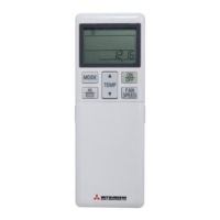
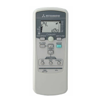
Wireless remote controller
1
Receiver backside
Wiring from receiver
CNL (3P, Whire)
X : White
Y : Black
Attached wiring
Signal terminal block
Connect
201801
PFA012D635