EasyManua.ls Logo

Mitsubishi Heavy Industries RCN-E1R - User Manual

Mitsubishi Heavy Industries RCN-E1R
5 pages
Print Icon
To Next Page IconTo Next Page
Loading...
ON : Normal (1ch)
OFF : Customized (2ch)
WIRELESS REMOTE CONTROLLER INSTALLATION MANUAL
WARNING
CAUTION
PFA012D620
1
Accessories
Remoto controller holder
1
AAA dry cell battery (RO3)
2
Wood screw for holder
2
Wireless remote controller
1
Fasten the wiring to the terminal securely and hold the cable securely so as not to apply unexpected stress on the terminal.
Loose connection or hold will cause abnormal heat generation or fire.
Make sure the power supply is turned off when electric wiring work.
Otherwise, electric shock, malfunction and improper running may occur.
Install a receiver unit where it is not exposed to direct sunrays or intense light from lighting fixtures.
Please make sure that you have all of the following accessories.
2
Installation of the controller holder
CAUTION DO NOT install it on the following places.
1. Places exposed to direct sunlight
3. Places near heat devices
5. High humidity places
• Adjust and keep the holder up right.
Tighten the screw to the end to avoid scratching the
remote controller.
• DO NOT attach the holder on plaster wall.
Installation tips for the remote controller holder
1
2. Hot surface or cold surface enough to generate condensation
4. Places exposed to oil mist or steam directly.
6. Uneven surface
1
Detach the back lid.
2
Insert the batteries. (two AAA batteries)
3
Reattach the back lid.
How to insert batteries
Wood screw
Holder for
remote controller
Ensure the correct
polarity when
inserting.
3
FDEN
Up to two receiver or wired remote controller can be installed in one indoor unit group.
When two receivers or wired remote controller are used, it is necessary to change SW on the PCB to set it as
slave.
Master/Slave setting when using plural remote controllers
Continuation on next page
2
PCB on the receiver has the following
switches to set the function.
Default setting is shown with mark.
Up to 16 indoor units can be connected.
1
Connect indoor units with each other with 2-core wires. As for size, refer to the following note.
2
The receiver wires must be connected only with the indoor unit that will be operated by the remote
controller directly.
3
Set the indoor unit address with SW2 on the indoor unit PCB from [0] to [F] so as not to duplicate.
Restrictions on the thickness and length of wire
(Maximun total extension 600m.)
S
tandard Within 100m x 0.3 mm
2
W
ithin 200m x 0.5 mm
2
W
ithin 300m x 0.75 mm
2
W
ithin 400m x 1.25 mm
2
W
ithin 600m x 2.0 mm
2
ATTENTION
In a system configured as shown above, up to two receivers are usable. If two receivers are used, it is
necessary to designate one of them as a slave by setting SW2. (For the method of changing the setting, refer to
Setting on site .) Since other receivers are not usable, do not couple the connectors for them. (Unless the
connector is coupled for a receiver, the LED will not be able to make any indication)
Control plural indoor units with one remote controller
Setting on site
1. Remove the front panel.
2. Remove four screws located on the back of the receiver and
detach the board.
3. Change the setting by the switch on PCB.
4.
When switch 1 is turned to off position, change the wireless remote controller setting.
(For the method of changing the setting, refer to Setting to avoid mixed communication
on page 4)
Refer to Wireless remote controller unit operation distance of
3
FDEN in case of plural setting.
To change setting
1
2 3 4
Default settings
SW1
Switch
ON
OFF
Receiver Backside
Prevents interference
during plural setting
Recei
ver master/slave
setting
Buzzer valid/Invalid
Auto restart
SW1
SW2
SW3
SW4
ON :
OFF :
Master
Sl
ave
ON :
OFF :
Valid
Invalid
ON :
OFF :
Valid
Invalid
Terminal block
Wireless
remote control unit
Indoor unit (16)
Address (F)
Indoor unit (2)
Address (1)
Indoor unit (1)
Address (0)
ReceiverReceiverReceiver
Receiver wires must be connected for one unit
only and leave other indoor units with open
connectors.
Question and Answer IconNeed help?

Do you have a question about the Mitsubishi Heavy Industries RCN-E1R and is the answer not in the manual?

Summary

Accessories

Installation of the controller holder

Installation tips for the remote controller holder

Offers specific advice for correctly attaching the remote controller holder, including screw tightening.

How to insert batteries

Details the step-by-step process for opening the lid and inserting batteries into the remote controller.

FDEN System Configuration

Setting on site

Explains how to configure the receiver's functions using DIP switches for various operational modes.

Master-Slave Setting for Multiple Controllers

Guides on setting up multiple receivers or wired controllers as master or slave units.

Controlling Multiple Indoor Units

Details the connection and addressing procedures for controlling multiple indoor units with a single remote.

Wire Thickness and Length Restrictions

Specifies the maximum wire gauges and total lengths allowed for connecting indoor units.

Wireless Remote Operation Distance

Defines the standard signal receiving range and factors affecting it, including lighting conditions.

Backup Button Operation

Describes the function of the physical backup switch on the receiver for manual operation.

Cooling Test Run Procedure

Outlines the procedure for performing a cooling test run command using the wireless remote and backup switch.

Reading the Two-Digit Display

Explains the meaning of various indications shown on the receiver's two-digit display, including errors.

Remote Controller Setup

Preventing Mixed Communication

Details how to customize the remote controller's signal to prevent interference with other units.

Disabling Auto Mode Operation

Explains how to configure the remote controller to prevent the selection of Auto mode for specific systems.

Overview

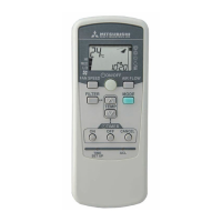
This document outlines the installation and operation of a wireless remote controller for air conditioning units, designated as model RCN-E1R.

Function Description

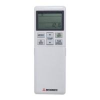
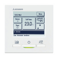
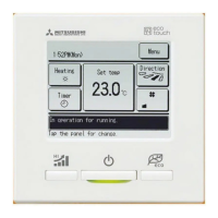
The wireless remote controller serves as the primary interface for users to manage their air conditioning units. It allows for various operations such as turning the unit on/off, adjusting fan speed, setting the desired room temperature, controlling airflow (swing louver), and programming ON/OFF timers. The system also includes a receiver unit that processes signals from the remote controller and communicates with the indoor unit(s).

The remote controller holder provides a convenient way to store the controller, and its installation is detailed to ensure optimal signal reception and durability. The system supports controlling multiple indoor units with a single remote controller, up to a maximum of 16 units, by establishing a wired connection between them and configuring their addresses.

A key feature is the "Master/Slave setting" for scenarios involving plural remote controllers or wired remote controllers within a single indoor unit group. In such cases, one receiver must be designated as a slave to prevent interference. The system also incorporates settings to avoid mixed communication and to disable the Auto mode operation, particularly for VRF systems (except heat recovery 3-pipe systems) where Auto mode is not applicable.

For emergency situations, a backup switch is provided on the receiver section. This allows manual operation of the air conditioner (start in automatic mode or stop operation) even if the wireless remote controller is unavailable or malfunctioning.

Important Technical Specifications

Wireless Remote Controller Unit Operation Distance:

  • Standard Signal Receiving Range:
    • Illuminance at the receiver area: 360 lux.
    • Condition: No lighting fixture located within 1m of the indoor unit in an ordinary office.
    • Effective operation distance can vary based on luminance around the receiver and reflections from walls.
    • Exposure to intensive light (direct sun, strong light) may reduce operability or prevent signal reception.
  • Plural Indoor Units Connection:
    • When using the interference-prevention setting, a minimum distance of 5m is required between units to prevent unintended responses.

Wiring Restrictions for Plural Indoor Units (Maximum Total Extension 600m):

  • Within 100m: 0.3 mm² wire
  • Within 200m: 0.5 mm² wire
  • Within 300m: 0.75 mm² wire
  • Within 400m: 1.25 mm² wire
  • Within 600m: 2.0 mm² wire
    • Receiver wires must be connected to only one indoor unit that will be operated by the remote controller directly. Other indoor units should have open connectors.

Power Supply:

  • The remote controller requires two AAA dry cell batteries (R03).

Receiver Unit Display:

  • A two-digit (7-segment) indicator on the receiver section provides various indications:
    • Displayed for one hour after power on.
    • Appears for 3.5 seconds when a "Stop" command is sent while the AC is not running.
    • Goes off when the unit starts operation.
    • Displays addresses for all connected units if no error records.
    • Displays error records if present.
    • Error records can be cleared by transmitting a "Stop" command while the backup switch is depressed.

Usage Features

Remote Controller Operation:

  • ON/OFF Button: Starts or stops the unit.
  • FAN SPEED Button: Cycles through HI, MED, and LO fan speeds.
  • AIR FLOW Button: Controls the swing louver.
  • OPERATION MODE Select Button: Cycles through AUTO, COOL, HEAT, FAN, and DRY modes.
  • ROOM TEMP/TIME SETTING Button (▲/▼): Adjusts room temperature and sets the current time.
  • ON TIMER Button: Sets the ON timer operation.
  • OFF TIMER Button: Sets the OFF timer operation.
  • TIMER CANCEL Button: Cancels timer settings.
  • FILTER Button: Resets the filter sign after cleaning.
  • RESET Switch: Resets the microcomputer.

Battery Insertion:

  1. Detach the back lid.
  2. Insert two AAA batteries, ensuring correct polarity.
  3. Reattach the back lid.

Controller Holder Installation:

  • Adjust and keep the holder upright.
  • Tighten screws to the end to prevent scratching the remote controller.
  • Do not attach the holder on plaster walls.
  • Avoid installing in places exposed to direct sunlight, near heat devices, high humidity, hot/cold surfaces (condensation risk), oil mist/steam, or uneven surfaces.

Site Settings (FDEN):

  • SW1 (Prevents interference during plural setting):
    • ON: Normal (1ch)
    • OFF: Customized (2ch)
  • SW2 (Receiver master/slave setting):
    • ON: Master
    • OFF: Slave
  • SW3 (Buzzer valid/invalid):
    • ON: Valid
    • OFF: Invalid
  • SW4 (Auto restart):
    • ON: Valid
    • OFF: Invalid
  • Changing Settings: Requires removing the front panel, detaching the board (after removing four screws from the back of the receiver), and then adjusting the switches on the PCB.

Setting to Avoid Mixed Communication:

  • Press ACL and AIR FLOW buttons simultaneously, or insert batteries while pressing AIR FLOW, to customize the signal.

Setting to Disable Auto Mode Operation:

  • Press ACL and MODE buttons simultaneously, or insert batteries while pressing MODE, to disable auto mode operation. This is necessary for VRF systems (except heat recovery 3-pipe systems) that do not support Auto mode.

Cooling Test Run Operation:

  1. Ensure safety and turn on power.
  2. Transmit a cooling operation command from the wireless remote control unit while the backup switch on the receiver is depressed.
  3. Pressing the backup switch during a test run will end it.
    • If the unit does not operate properly, check wiring and consult inspection guides.

Maintenance Features

Filter Sign Reset:

  • The FILTER button on the remote controller is used to reset (turn off) the filter sign after the filter has been cleaned.

Battery Replacement:

  • When batteries are removed, the remote controller's settings will revert to default. Users must reset the settings after replacing batteries. Instructions for this are also provided in the user's manual attached to the air conditioner.

Error Record Display and Clearing:

  • The two-digit indicator on the receiver displays error records if any are present.
  • Error records can be cleared by transmitting a "Stop" command from the wireless remote control unit while the backup switch is depressed.

Mitsubishi Heavy Industries RCN-E1R Specifications

General IconGeneral
BrandMitsubishi Heavy Industries
ModelRCN-E1R
CategoryRemote Control
LanguageEnglish

Related product manuals