Do you have a question about the Mitsubishi Heavy Industries SKM22ZF-S and is the answer not in the manual?
| Cooling Capacity | 2.2 kW |
|---|---|
| Heating Capacity | 2.5 kW |
| Power Supply | 220-240 V, 50 Hz |
| Refrigerant | R32 |
| Indoor Unit Dimensions (W x H x D) | 845 x 275 x 228 mm |
| Outdoor Unit Dimensions (W x H x D) | 645 x 540 x 275 mm |
| Type | Split System |
Details on connectivity, capacities, inverter technology, and operational modes for flexibility and efficiency.
Explanation of the model naming convention for identifying unit type, capacity, and system.
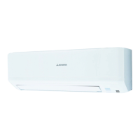
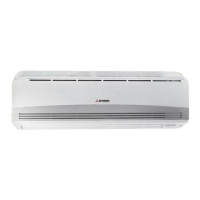
Technical specifications for indoor and outdoor units, including capacity, noise levels, dimensions, and electrical data.
Defines operating limits for indoor/outdoor air temperatures, and piping length/height constraints.
Provides detailed dimensional drawings and measurement points for indoor and outdoor units.
Illustrates the refrigerant circuit and component layout for various models, including pipe sizes.
Offers charts for correcting capacity based on temperature and piping length.
Diagrams showing the electrical connections, wiring symbols, and color codes for units.
Explains functions and indicators of the wireless remote control for unit operation.
Describes the function of the physical unit ON/OFF button for basic operation.
Details the procedure for forced drain motor operation under specific conditions.
Explains the function that resumes operation automatically after a power interruption.
Describes how to adjust the air direction flap using the remote control.
Outlines the comfortable timer function for setting operation start times based on room conditions.
Details fan speed control and capacity management during cooling operation.
Details fan speed control and capacity management during heating operation.
Explains how the unit determines and switches operating modes automatically based on conditions.
Describes how the unit determines the operating mode based on previously set or detected conditions.
Covers external inputs and outputs for control and signaling between units and controllers.
Explains how to control operation based on external signals and jumper settings.
Details various protective controls like frost prevention, overload protection, and dew condensation prevention.
Crucial safety warnings and precautions for installation and handling of the air conditioning system.
Instructions for mounting and installing the indoor unit correctly, including drilling and fixing.
Guidance on installing the wired or wireless remote control units, including mounting and wiring.
Guidelines for selecting the location and installing the outdoor unit, considering space and environmental factors.
Details on power supply connections, wiring specifications, and inter-unit wiring.
Information on pipe limits, diameters, materials, and connection procedures for R410A.
Steps for conducting test runs, installation checks, and customer explanation.
Instructions for installing wired remote controls and optional super link adapters.
Procedures for installing optional accessories like air inlet grilles, filters, and duct joints.
A systematic guide to diagnosing and resolving operational issues using error codes and inspection steps.
Procedures for evacuation, refrigerant charging, and recovery of refrigerant for maintenance.
Covers R410A adoption, chemical characteristics, pressure properties, and safety.
Safety precautions and considerations for R410A installation and servicing.
Details piping materials, joints, processing methods, and brazing techniques.
Covers tools, procedures, and applicability for R410A systems.
Procedures and equipment for recovering R410A refrigerant.