Do you have a question about the Mitsubishi Heavy Industries SKM50ZF-S and is the answer not in the manual?
| Brand | Mitsubishi Heavy Industries |
|---|---|
| Model | SKM50ZF-S |
| Category | Air Conditioner |
| Language | English |
Details on connectable units, piping lengths, and inverter/fuzzy control features.
Explanation of the model name structure for identifying product specifications.
Specifications for indoor units SKM20ZF-S to 50ZF-S, including capacity, noise, and dimensions.
Specifications for outdoor units SCM40ZF-S and SCM45ZF-S, covering capacity, power, and dimensions.
Heating and cooling operation data for SCM40ZF-S, detailing indoor unit combinations and power consumption.
Specifies operating limits for air temperatures, piping lengths, and connected units for various models.
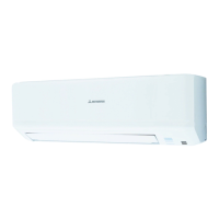
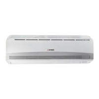
External dimensions and mounting details for SKM and STM indoor units.
External dimensions and mounting details for SRRM and SCM outdoor units.
Diagram illustrating the refrigerant piping system for the SCM40ZF-S model.
Graphs showing capacity correction factors based on temperature variations for cooling and heating.
Capacity corrections based on piping length and outdoor frosting conditions.
Wiring diagrams for various indoor units (SKM, STM, SRRM) showing component connections and color codes.
Explanation of wireless remote control operation section, buttons, and indicator lights.
Details on indicator lights for SKM, STM, and SRRM units during operation and status.
Instructions for turning the unit on and off using the ON/OFF button on the remote or unit.
Procedure for forcing drain motor operation, including reset conditions and details.
Explanation of the auto restart function after power outages and its configuration.
Control of flap direction using the AIRFLOW button on the wireless remote control.
Description of the comfortable timer for setting operation start time based on room temperature.
Overview of capacity control, mode switching, and component operation in cooling mode.
Overview of capacity control, mode switching, and component operation in heating mode.
How the unit determines operation mode and adjusts settings based on temperatures.
How the unit determines operation mode based on room and outdoor temperatures.
Table showing relationship between remote control signals and setting temperature values.
Explains how operating modes are determined and the conditions for fan-only operation.
Details on external control outputs and input signals for integrated system control.
Control mechanisms for enabling or disabling unit operation via jumper wires and input signals.
Frost prevention control for indoor heat exchanger during cooling/dehumidifying operations.
Function to prevent drain water overflow, detailing operation conditions and reset.
Control to prevent dew condensation during cooling/dehumidifying, detailing conditions and operation.
High pressure control to prevent abnormal operation during heating using indoor heat exchanger sensor.
Protective control to prevent freezing of the cycle during cooling/dehumidifying operations.
Operation of the crankcase heater to warm the compressor for efficient heating startup.
Prevents improper operation by controlling compressor and indoor fan speed during startup.
Control to protect the unit from cooling overload due to high outdoor temperature.
Protection control for cooling at low load, adjusting decision speed based on outdoor air temperature.
Protective control for cooling at low outdoor temperatures, adjusting fan speed based on heat exchanger temperature.
Control to prevent heating overheating due to high outdoor temp., adjusting fan speed and limit.
Protective control for heating at low outdoor temperatures, adjusting fan speed and decision speed.
Control to reduce decision speed or stop compressor when current exceeds set amperage.
Detects converter output current and stops compressor if it exceeds the set value.
Protects outdoor fan motor by stopping it if it operates at low speed for an extended period.
Protection against compressor overheating using discharge pipe sensor, with speed reduction and stop controls.
Protects power transistor from overheating by reducing decision speed or stopping the compressor.
Stops compressor if serial signals from indoor units are not received for a specified duration.
Detects compressor lock and stops the compressor if the motor fails to rotate within a specified time.
Protection against discharge pipe sensor disconnection, adjusting decision speed or stopping the unit.
Detects outdoor unit failures like low input current or repeated 0 rps signals, stopping the compressor.
Tables detailing outdoor fan speed regulation based on decision speed for cooling and heating.
General safety warnings and precautions for installation and operation of the air conditioning system.
Installation instructions for SKM wall-mounted, STM ceiling cassette, and SRRM ducted indoor units.
Cautions for piping installation from the left and rear of the unit, including drain hose handling.
Installation instructions for STM 4-way ceiling cassette units, including cautions and mounting.
Instructions for installing the unit when embedded into the ceiling, including bolt placement and drainage.
Detailed instructions for drain piping installation, including slope, insulation, and avoiding traps.
Installation cautions and dimensions for SRRM ducted indoor units.
Procedure for mounting the remote control and its batteries, including pillar/wall fixing.
Guidelines for selecting location and steps for physically installing the outdoor unit.
Instructions for connecting power lines and crossover wires between indoor and outdoor units.
Limits, connection steps, air purging, and additional charging for refrigerant piping.
Steps for inspection, test run, and handling after installation, including check points.
Installation of optional parts like remote controls, super link adapters, and ducted unit accessories.
General troubleshooting steps and self-diagnosis indications for identifying unit problems.
Table detailing self-diagnosis codes, causes, and conditions of flashing indicators for unit errors.
Step-by-step inspection procedures for sensor errors, fan motor, current issues, and compressor problems.
Procedures for checking the indoor unit circuit board and fan motor for faults.
Steps to verify the correct functioning of the remote control unit.
Step-by-step diagnosis for inverter failures, checking fuses, varistors, capacitors, inductors, and transistors.
Specific inspection points for the outdoor unit's power supply, serial signals, lamps, and components.
Introduction to R410A refrigerant, its characteristics, and safety considerations for installation.
Details on R410A adoption, its chemical properties, and comparison with R22.
Safety precautions for R410A installation/servicing due to its high pressure and specific requirements.
Information on piping materials, joints, processing, flux, brazing, and tools for R410A.
Procedures for R410A installation, unit replacement, retrofitting, recharging, and recovery.
Steps for air purging, gas leakage inspection, and additional refrigerant charging.
Procedures for removing the unit, installing a new one, and replacement considerations.
Warning against retrofitting R22 systems with R410A, which can cause malfunction or serious problems.
Steps for recharging refrigerant when necessary, including connecting hoses and using an electronic balance.
General procedures and equipment checks for recovering refrigerant safely and legally.
List of accessories and tools required for R410A refrigerant recovery, such as cylinders, driers, and hoses.