Do you have a question about the Mitsubishi Heavy Industries SRF50ZIX-S and is the answer not in the manual?
| Cooling Capacity | 5.0 kW |
|---|---|
| Heating Capacity | 6.0 kW |
| Energy Efficiency Ratio (EER) | 3.21 |
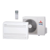
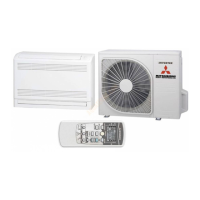
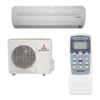
| Type | Split System |
| Refrigerant | R32 |
| Power Consumption (Cooling) | 1.56 kW |
| Outdoor Unit Noise Level | 50 dB(A) |
| Power Supply | 220-240V, 50Hz |
Details electrical wiring for the wall-mounted indoor unit.
Explains the refrigerant piping system for wall-mounted units.
Presents noise level data for indoor and outdoor units of wall-mounted type.
Provides sensible heat capacity data for wall-mounted units.
Covers general application data for wall-mounted units.
Details the installation process for the indoor unit of wall-mounted type.
Details the installation process for the outdoor unit of wall-mounted type.
Explains operation control functions via microcomputer for wall-mounted units.
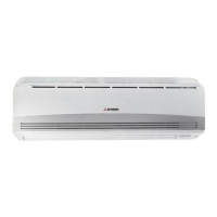
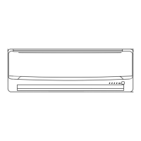
Specifics for the wall-mounted indoor unit, including specs, dimensions, wiring.
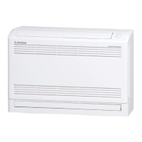
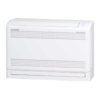
Specifics for the floor-standing indoor unit, including specs, dimensions, wiring.
Details exterior dimensions for the outdoor unit.
Details electrical wiring for the outdoor unit.
Details electrical wiring for the indoor unit models SRK20ZIX-S to 60ZIX-S.
Details the piping system for SRK20/25/35ZIX-S models.
Details the piping system for SRK50/60ZIX-S models.
Noise level data for the indoor unit, SRK20ZIX-S.
Noise level data for the outdoor unit, SRC20ZIX-S.
Noise level data for the indoor unit, SRK25ZIX-S.
Noise level data for the outdoor unit, SRC25ZIX-S.
Noise level data for the indoor unit, SRK35ZIX-S.
Noise level data for the outdoor unit, SRC35ZIX-S.
Noise level data for the indoor unit, SRK50ZIX-S.
Noise level data for the outdoor unit, SRC50ZIX-S.
Noise level data for the indoor unit, SRK60ZIX-S.
Noise level data for the outdoor unit, SRC60ZIX-S.
Sensible heat capacity data for SRK20ZIX-S model.
Sensible heat capacity data for SRK25ZIX-S model.
Sensible heat capacity data for SRK35ZIX-S model.
Sensible heat capacity data for SRK50ZIX-S model.
Sensible heat capacity data for SRK60ZIX-S model.
Crucial safety precautions to be followed during indoor unit installation.
General directions for installing the indoor unit.
Specifies the required installation space for the indoor unit.
Important cautions to observe during the installation process.
Guidance on selecting an appropriate location for indoor unit installation.
Essential safety precautions for outdoor unit installation.
Checklist of items to verify before commencing outdoor unit installation.
Lists accessories required for outdoor unit installation.
Lists optional parts for outdoor unit installation.
Lists the tools required for outdoor unit installation.
Outlines restrictions for unit installation and usage related to piping.
Guidelines for determining the correct refrigerant pipe size.
Crucial safety measures for refrigerant piping work.
Instructions for safely carrying and moving the unit.
Guidance on choosing an appropriate installation location for the unit.
Specifies the required installation space around the unit.
Details the physical installation steps for the unit.
Important note regarding copper pipe selection for R410A.
Important step regarding pipe work.
Instructions on removing the side cover for access.
Refers to indoor unit manual for electrical cabling details.
Checks to be performed after the main installation is done.
Instructions for safely carrying and moving the unit.
Guidance on choosing an appropriate installation location for the unit.
Specifies the required installation space around the unit.
Details the physical installation steps for the unit.
Important note regarding copper pipe selection for R410A.
Important step regarding pipe work.
Instructions on removing the side cover for access.
Steps for charging refrigerant into the system.
Refers to indoor unit manual for electrical cabling details.
Checks to be performed after the main installation is done.
Explains operation control functions via the remote controller.
Details on setting the comfortable ON timer.
Describes the sleep timer operation.
Explanation of how to set the OFF timer.
Steps for setting the installation location.
Details the operation of key components during heating.
Explains control details for different operation modes like Fuzzy and Hot Keep.
Describes the conditions and process for defrosting operation.
Details the operation of key components during cooling.
Explains control details for cooling operation patterns like Fuzzy.
How the unit determines the operation mode automatically.
Protective control to prevent frost during cooling or dehumidifying.
Protective control to prevent overload during cooling operation.
Protective control to prevent high pressure during cooling operation.
Details electrical wiring for the floor-standing indoor unit.
Explains the refrigerant piping system for floor-standing units.
Presents noise level data for floor-standing units.
Provides sensible heat capacity data for floor-standing units.
Covers general application data for floor-standing units.
Details the installation process for the indoor unit of floor-standing type.
Details the installation process for the outdoor unit of floor-standing type.
Explains operation control functions via microcomputer for floor-standing units.
Details electrical wiring for the indoor unit of floor-standing type.
Details the piping system for SRF25/35ZIX-S models.
Details the piping system for SRF50ZIX-S model.
Noise level data for the indoor unit, SRF25ZIX-S.
Noise level data for the outdoor unit, SRC25ZIX-S.
Noise level data for the indoor unit, SRF35ZIX-S.
Noise level data for the outdoor unit, SRC35ZIX-S.
Noise level data for the indoor unit, SRF50ZIX-S.
Noise level data for the outdoor unit, SRC50ZIX-S.
Sensible heat capacity data for SRF25ZIX-S model.
Sensible heat capacity data for SRF35ZIX-S model.
Sensible heat capacity data for SRF50ZIX-S model.
Crucial safety precautions to be followed during indoor unit installation.
General directions for installing the indoor unit.
Specifies the required installation space for the indoor unit.
Important cautions to observe during the installation process.
Guidance on selecting an appropriate location for indoor unit installation.
Installation details for SRC25/35ZIX-S outdoor units.
Installation details for SRC50ZIX-S outdoor unit.
Explains operation control functions via the remote controller.
Details on setting the comfortable ON timer.
Describes the sleep timer operation.
Explanation of how to set the OFF timer.
Details the operation of key components during heating.
Explains control details for different operation modes like Fuzzy and Hot Keep.
Describes the conditions and process for defrosting operation.
Details the operation of key components during cooling.
Explains control details for cooling operation patterns like Fuzzy.
How the unit determines the operation mode automatically.
Protective control to prevent frost during cooling or dehumidifying.
Protective control to prevent overload during cooling operation.
Protective control to prevent high pressure during cooling operation.
Procedures for troubleshooting electrical equipment issues.
Step-by-step procedure for displaying service data.
Explanation of self-diagnosis data recorded by the unit.
Phenomena observed in the indoor unit.
Procedure for checking the indoor PCB.
Procedure for checking the indoor unit fan motor.
Checks for power source and serial signal connections on the outdoor unit.
Procedure to inspect sensor resistance values.
Procedure to inspect the power transistor.
Procedure to inspect the electronic expansion valve.
Procedure to inspect the outdoor fan motor.
Procedure for inspecting the electronic expansion valve independently.
Steps to check the outdoor PCB output.
Procedure to check the fan motor's resistance.
Procedure for purging impurities using a vacuum pump.
Steps for charging refrigerant into the system.
Provides an overview of refrigerant R410A and its characteristics.
Details on the adoption and properties of R410A refrigerant.
Safety precautions for R410A installation and servicing.
Covers the installation of refrigerant piping.
Specifies materials and joints for refrigerant piping.
Steps and precautions for flare processing of pipes.
Classification and storage methods for refrigerant piping materials.
Procedures for processing connected parts for brazing.
Details on different types of brazing filler metals.
Method for preventing oxidation during the brazing process.
Lists tools specifically required for R410A systems.
Details about the gauge manifold for R410A.
Details about pressure-resistant charge hoses for R410A.
Details about electronic balance for accurate refrigerant charging.
Torque wrench specifications for R410A flare nut connections.
Steps for air purging and gas leakage inspection using a vacuum pump.
Procedure for additional refrigerant charging based on piping length.
Procedure for removing the unit, including refrigerant recovery.
Steps for installing the unit following new installation procedures.
Procedure for purging impurities using a vacuum pump.
Steps to prepare for refrigerant recovery equipment.
How to connect refrigerant recovering equipment.
Details on types and usage of recovering cylinders.
Information on the desiccant container for R410A recovery.
Details on connection hoses for refrigerant recovery.