-
9
-
'18 • SCM-T-251
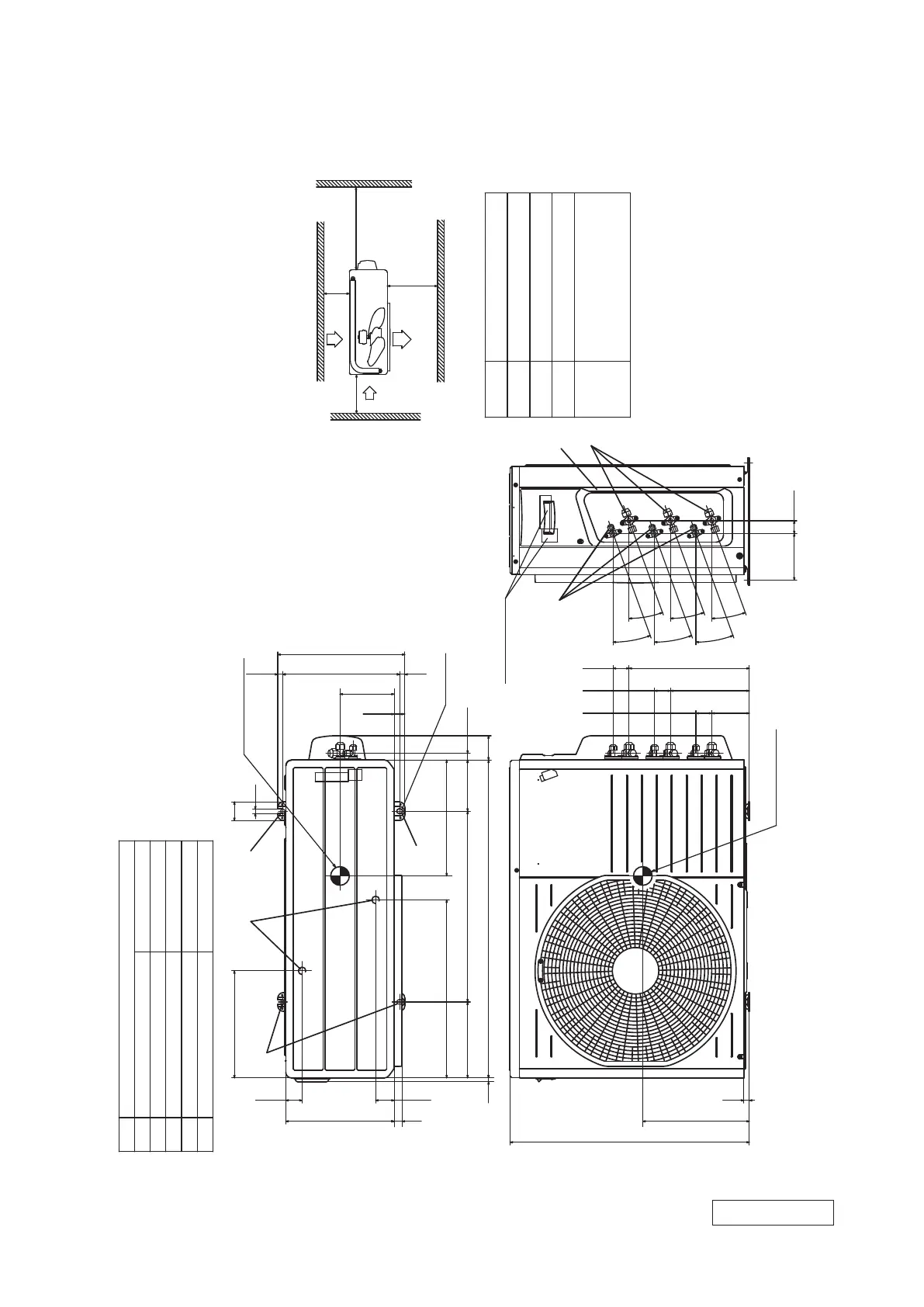
1.2 Exterior dimensions
Models SCM50ZS-S1, 60ZM-S1
RWC000Z318
Unit:mm
L2
Inlet
Outlet
Inlet
L3
L1
Service
space
( )
L4
L2
L3
L4
L1
100
100
No obstacles
600
Installation space
or more
or more
or more
ф9.52 (3 ⁄ 8") (Flare)
Content
C
Pipe / cable draw-out hole
D
E
Anchor bolt hole
Drain discharge hole
Symbol
B
A
Service valve connection (gas side)
M10-12x4 places
ф20x2 places
Service valve connection (liquid side)
ф6.35 (1 ⁄ 4") (Flare)
43.5
286.4
49.6
136.9
14 312.5
50
12
13.5
340
640
15
100.3 42.7
124.1 34.6
211 42.7
20°
20°
20°
20°
321.7 42.7
20°
20°
290
476
203.1 510
850
14.6
2-12x16
17.9
65
(Service space or
electrical parts)
285
310
Slot hole
145
21
10
Minimum installation space
Center of gravity
D
B
A
C
Terminal block
E
Center of gravity
E
E
Notes
⑴ The unit must not be surrounded by walls on the four sides.
⑵ The unit must be fixed with anchor bolts. An anchor bolt must not
protrude more than 15mm.
⑶ If the unit is installed in the location where there is a possibility of
strong winds, place the unit such that the direction of air from the
outlet gets perpendicular to the wind direction.
⑷ Leave 200mm or more space above the unit.
⑸ The wall height on the outlet side should be 1200mm or less.
⑹ The model name label is attached on the right side of the unit.
 Loading...