Do you have a question about the Mitsubishi Heavy Industries SRK71ZE-S1 and is the answer not in the manual?
| Cooling Capacity | 7.1 kW |
|---|---|
| Heating Capacity | 8.0 kW |
| Energy Efficiency Ratio (EER) | 3.21 |
| Power Supply | 220-240 V, 50 Hz |
| Indoor Unit Dimensions (W x H x D) | 1197 x 339 x 262 mm |
| Energy Efficiency Class Cooling | A++ |
| Energy Efficiency Class Heating | A+ |
| Refrigerant | R32 |
| Energy Efficiency Ratio (Cooling) | 3.21 |
| Indoor Unit Dimensions (HxWxD) | 339 x 1197 x 262 mm |
Specifications and details for SRK20ZD-S1, SRK25ZD-S1, SRK35ZD-S1, SRK50ZD-S1 models.
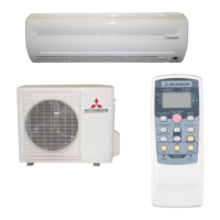
Specifications and details for SRK63ZE-S1, SRK71ZE-S1 models.
Provides specific features, how to read model names, and self-diagnosis functions.
Covers specifications, usage limitations, dimensions, piping, and selection charts.
Details electrical wiring diagrams and components.
Describes operation control functions via remote and on-unit buttons.
Safety precautions and guidelines for unit installation.
Procedures for troubleshooting electrical issues and general servicing.
Manual for refrigerant piping installation and servicing for R410A systems.
Specifications and details for SRK20HD-S1, SRK20HC-S2, SRK28HD-S1, SRK28HC-S2, SRK40HD-S1, SRK40HC-S2 models.
Specifications and details for SRK50HE-S1, SRK56HE-S1 models.
Specifications and details for SRK63HE-S1, SRK71HE-S1 models.
Provides specific features, how to read model names, and self-diagnosis functions.
Covers specifications, usage limitations, dimensions, piping, and selection charts.
Details electrical wiring diagrams and components.
Describes operation control functions via remote and on-unit buttons.
Safety precautions and guidelines for unit installation.
Procedures for troubleshooting electrical issues and general servicing.
Manual for refrigerant piping installation and servicing for R410A systems.
Specifications and details for SRK20CD-S1, SRK20CC-S1, SRK28CD-S1, SRK28CC-S1, SRK40CD-S1, SRK40CC-S1 models.
Specifications and details for SRK50CE-S1, SRK56CE-S1 models.
Specifications and details for SRK63CE-S1, SRK71CE-S1 models.
Provides specific features, how to read model names, and self-diagnosis functions.
Covers specifications, usage limitations, dimensions, piping, and selection charts.
Details electrical wiring diagrams and components.
Describes operation control functions via remote and on-unit buttons.
Safety precautions and guidelines for unit installation.
Procedures for troubleshooting electrical issues and general servicing.
Manual for refrigerant piping installation and servicing for R410A systems.