Do you have a question about the Mitsubishi MOTORS 4M41 and is the answer not in the manual?
| Engine Type | Diesel |
|---|---|
| Fuel Type | Diesel |
| Cylinder arrangement | Inline-4 |
| Valvetrain | DOHC |
| Fuel System | Common rail direct injection |
| Bore x Stroke | 98.5 mm x 105 mm |
| Compression Ratio | 17.0:1 |
| Displacement | 3.2 L |
| Aspiration | Turbocharged |
Service specifications for the glow plug, including resistance value.
Service specifications for the intake manifold, including throttle body temperature.
Service specifications for the turbocharger, including actuator operating pressure.
Specifications for camshaft end play, lobe lift, bend, and rocker radial play.
Specifications for injection nozzle, including opening pressure and pre-lift.
Specifications for cylinder head and valve mechanism, including valve spring and distortion.
Specifications for intake and exhaust valves: stem diameter, sinkage, and seat angle.
Specifications for valve guides and seats: clearance, width, and bottom surface distortion.
Specifications for vacuum pump degree of vacuum and pump speed.
Specifications for timing gears and balance shafts: backlash, end play, and clearances.
Specifications for oil pump clearances: shaft-to-case, side, and tip clearances.
Specifications for oil cooler and oil filter components: valve opening pressures.
Specifications for piston and connecting rod: protrusion, clearances, end play, bend, and twist.
Specifications for crankshaft and crankcase: end play, bend, out-of-roundness, conicity, and distortion.
Specification for balance shaft bush clearance.
Torque values for glow plug connection plate and glow plug.
Torque values for cooling fan, V-belt, and water pump components.
Torque values for water hoses and pipes: eyebolt, coolant sensor.
Torque values for intake manifold components: sensors, gas filter assembly.
Torque values for turbocharger assembly components: eyebolts, nuts, bolts.
Torque value for exhaust manifold nut.
Torque values for injection pump assembly, pipes, and stays.
Torque values for rocker cover, camshaft holder, and camshaft components.
Torque values for injection nozzle components: pipes, eyebolts, retaining nuts.
Torque values for cylinder head and valve mechanism components: bolts, joints.
Torque values for vacuum pump components: eyebolts, cover bolts.
Torque values for timing gear case components: pulley bolts, cap nuts.
Torque values for timing gear and balance shaft components: bolts, nuts.
Torque values for oil pump components: balance shaft bolts, cover screws.
Torque values for oil cooler and oil filter components: element nuts, plugs.
Torque values for oil pan, oil jet, and drain plug.
Torque value for connecting rod cap mounting nut.
Torque values for drive plate assembly mounting bolts.
Torque values for crankshaft and crankcase components: dust cover, main bearing bolts.
Torque values for hexagon head bolts and stud bolts by strength code and diameter.
Torque values for hexagon flange bolts by strength code, head mark, and diameter.
Torque values for hexagon nuts by strength code, head mark, diameter, and thread type.
Torque values for hexagon flange nuts by strength code, head mark, diameter, and thread type.
Specified sealants for various engine mating surfaces.
Precautions and procedures for applying FIPG: bead size, continuity, location.
Tools for crankshaft pulley removal/installation and injection pump assembly.
Tools for retaining nut removal/installation and nozzle cleaning.
Tools for injection nozzle opening pressure adjustment and lift checking.
Tools for holding camshaft sprocket and for valve spring compression/removal.
Tools for valve guide removal/installation and valve seat installation.
Tools for valve stem seal, idler gear bush, idler sprocket bush, and piston rings.
Tools for connecting rod bush, piston guide, gear puller, and balance shaft bush.
Tools for injection pump gear removal and assembly.
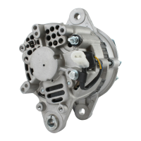
Steps and diagram for removing and installing the generator assembly.
Inspection points for the generator and cautions for handling to prevent damage.
Diagram and steps for removing and installing glow plugs.
Procedure for inspecting glow plug resistance and replacement criteria.
Diagram and steps for removing and installing cooling fan, V-belt, and water pump.
Diagram and steps for removing and installing water hoses and pipes.
Caution regarding O-ring installation and avoiding engine oil contact.
Diagram and steps for removing and installing the thermostat and related components.
Caution regarding O-ring installation, emphasizing avoiding engine oil.
Procedure for installing the thermostat with its jiggle valve in the uppermost position.
Diagram and steps for EGR valve assembly removal/installation for specific models.
Diagram and steps for EGR valve assembly removal/installation for 2002 Pajero models.
Procedures for cleaning carbon deposits from EGR valve and cooler, with cautions.
Methods for inspecting EGR cooler for air leaks in exhaust and coolant passages.
Diagram and steps for intake manifold removal/installation for specific models.
Diagram and steps for intake manifold removal/installation for 2002 Pajero models.
Procedure for fitting the gasket to the cylinder head for intake manifold installation.
Inspection of throttle valve movement, damage, and resistance measurements.
Diagram and steps for removing and installing the turbocharger assembly.
Lubricating turbocharger parts and checking actuator pressure.
Diagram and steps for removing and installing the exhaust manifold.
Diagram and steps for removing and installing the injection pump assembly.
Procedure for removing fuel injection pipe while locking delivery valve holder.
Steps for installing injection pump assembly, including timing and gear alignment.
Confirming gear alignment and positioning injection pump assembly.
Procedure for tightening fuel injection pipe union nut.
Diagram and steps for removing and installing injection pump gear and related components.
Using a special tool to remove the injection pump gear.
Installing flange plate while aligning mating marks.
Clamping gear, removing locating pin, and installing sub gears and springs.
Fitting snap ring, aligning sub gear, and installing bolt and locating pin.
Diagram for removal and installation of rocker cover, camshaft holder, and camshaft.
Measuring camshaft end play and replacing defective parts if limit is exceeded.
Cautions for removing inversely threaded bolt and meshing camshaft sprockets.
Cautions regarding inversely threaded bolt installation direction.
Installing rocker cover gasket and assembly, with cautions.
Measuring camshaft lobe lift and replacing if limit is exceeded.
Measuring camshaft bend and replacing if limit is exceeded.
Measuring oil clearance at camshaft journals and replacing defective parts.
Measuring radial play at the rocker roller and replacing defective parts.
Diagram and steps for removing and installing the injection nozzle assembly.
Cautions on fuel flammability, cleaning, and component combinations for injection nozzles.
Procedure for checking injection nozzle valve opening pressure using a tester.
Procedure for checking injection nozzle spray patterns and identifying good/bad types.
Checking injection nozzle for dribbling after pressure increase.
Using a special tool to remove and install the retaining nut for the injection nozzle.
Procedures for cleaning nozzle tip and needle valve using special tools and cautions.
Inspection of needle valve sliding and replacement criteria.
Sequence for adjusting and checking injection nozzle assembly parts.
Steps for fitting parts, lift piece, nozzle tip, and securing with retaining nut.
Attaching nozzle holder to tester and measuring 1st valve opening pressure.
Checking needle valve full lift using special tools like plate, holder, and nut.
Connecting dial gauge and measuring needle valve lift at specific pressure.
Attaching nozzle holder to tester, zeroing dial gauge, and bleeding air.
Reading dial gauge for prelift and replacing parts if readings deviate from standard.
Operating tester to increase pressure and checking for needle valve lift.
Adjusting pressure by changing shims if dial gauge readings deviate from standard.
Removing special tools and performing final check of 1st valve opening pressure, spray form, and seat tightness.
Diagram and steps for removing and installing cylinder head and valve components.
Caution regarding cylinder head bolts and timing chain removal. Method 1 for valve cotter removal.
Installing valve spring and valve stem seal.
Procedures for removing and installing exhaust and intake valve guides.
Procedures for removing and installing exhaust and intake valve seats.
Caution for gasket removal and stepwise loosening of cylinder head bolts.
Using a special tool to hold camshaft sprockets while removing cylinder head assembly.
Using special tools MD998772 and MD998784 to remove valve cotters.
Using special tool MD999597 to compress valve spring for cotter removal.
Using special tools to install valve cotters by depressing the valve spring retainer.
Removing valve guides using a special tool.
Removing shrink-fitted valve seats by grinding and pulling.
Measuring seat hole diameter, selecting oversize seats, and pressing them in.
Measuring guide hole diameter, selecting oversize guides, and installing them.
Applying oil to seal lip and pressing it into position with a special tool.
Installing the valve spring with the blue painted end facing upward.
Using special tools to install valve cotters by depressing the spring retainer.
Securing retainer holder, adjusting stay position, and installing valve cotters.
Using special tool to compress valve spring for installing valve cotters.
Selecting and installing cylinder head gasket based on piston protrusion and crankcase marks.
Cautions on punch marks for cylinder head bolts and ensuring proper fit.
Applying specified sealant to front plate for cylinder head gasket installation.
Detailed procedure for tightening cylinder head bolts in stages and sequences.
Fitting the gasket and tensioner for the cylinder head assembly.
Installing tensioner, cranking engine, and cautions for chain damage.
Checking valve stem diameter for wear and replacing if below specified limit.
Checking valve seat angle and margin, and replacing if limit is exceeded.
Checking valve seat width and sinkage, and caution for proper seating after correction.
Checking clearance between valve and valve guide and replacing if limit is exceeded.
Checking valve seating condition using minium pattern and determining corrective action.
Measuring cylinder head bottom surface distortion and replacing if limit is exceeded.
Grinding valve margin, seat width, and lapping for proper seating.
Applying lapping compound, striking valve, washing, and checking seat contact.
Performing valve lapping with a valve lapper and replacing valve seat if necessary.
Diagram and steps for removing and installing the vacuum pump assembly.
Connecting vacuum tank and gauge, and checking vacuum degree and pump speed.
Diagram and steps for removing and installing the timing gear case and related parts.
Removing crankshaft pulley using a special tool.
Applying sealant to timing gear case joint surface and installing it.
Applying oil to seal lip and pressing it into the timing gear case.
Diagram showing components for timing gear and balance shaft removal and installation.
Measuring backlash between gears and replacing defective parts if limit is exceeded.
Measuring end play of balance shafts and idler gears, and replacing if limit is exceeded.
Using a special tool to remove the idler gear bush.
Using a special tool to remove the idler sprocket bush.
Press-fitting idler sprocket bush into idler gear using a special tool.
Installing idler gear and sprocket assembly onto idler shaft, aligning marks.
Assembling and installing balance shaft LH assembly, with cautions for O-ring and bush.
Press-fitting idler gear bush LH into idler gear using a special tool.
Installing idler gear LH assembly onto idler shaft, aligning marks.
Assembling and installing balance shaft RH assembly, aligning marks on gears.
Holding camshaft sprocket, aligning marks, and installing timing chain with specific link plates.
Aligning stamped lines, checking chain slack, and replacing timing chain if limit is exceeded.
Inspecting tensioner lever for cracks and checking tension lever shaft clearance.
Replacing guide plate if it shows cracks or flakes.
Checking clearance between idler gear bush and shaft, and replacing if limit is exceeded.
Checking clearance between idler sprocket bush and shaft, and replacing if limit is exceeded.
Diagram and steps for removing and installing the oil pump assembly and its components.
Inspecting shaft-to-case, gear height-to-case, and gear tooth crest-to-case clearances.
Diagram and steps for removing and installing the oil filter and oil cooler assembly.
Cleaning and inspecting the oil cooler element for carbon deposits and air leaks.
Cleaning the oil cooler assembly surface and applying oil to the filter gasket.
Diagram and steps for removing and installing the oil pan, oil strainer, and oil jet.
Applying sealant to crankcase and timing gear case, then installing oil pan with specified bead.
Diagram showing components for piston and connecting rod removal and installation.
Cautions on connecting rod bolt removal and tightening, and piston ring removal.
Using a special tool to remove each piston ring.
Checking piston protrusions from crankcase top and selecting gasket thickness.
Measuring connecting rod end play and replacing defective parts if limit is exceeded.
Cautions regarding punch marks on connecting rod nuts and bolts.
Removing piston pin using a push-out bar, with notes on warming the piston.
Using a special tool to remove the connecting rod bush.
Checking bolt hole, applying oil, and fitting connecting rod bolt with a press ram load.
Using special tool to install connecting rod bush, applying oil, and reaming for clearance.
Using pistons with matching size marks and cautions about size mismatches.
Installing piston pin, connecting rod, and piston, and checking for smooth movement.
Installing oil rings and compression rings with correct end gap positioning.
Checking piston ring gaps, size marks, and using vinyl hose for protection during assembly.
Installing piston/rod assembly, applying oil, tightening connecting rod cap nuts in stages.
Methods for selecting and installing connecting rod bearings based on measurements and identification colors.
Cautions on bearing installation, checking free span, and replacing them as a set.
Measuring clearance and adjusting crankshaft O.D. if undersize bearings are used.
Measuring piston ring end gap and replacing rings if limit is exceeded.
Measuring clearance between piston rings and grooves, and cautions for replacement.
Measuring clearance between piston pin and piston, and piston pin and connecting rod bush.
Measuring bend and twist of connecting rod using an aligner and replacing if limit is exceeded.
Diagram and steps for removing and installing the drive plate assembly.
Heating the ring gear evenly and tapping it to remove.
Attaching adaptor plate and crankshaft adaptor to drive plate assembly.
Heating the ring gear and fitting it onto the drive plate.
Checking the ring gear for damage and abnormal wear.
Diagram showing components for crankshaft and crank case removal and installation.
Measuring crankshaft end play and replacing thrust plates if limit is exceeded.
Gradually loosening bolts in sequence for lower crankcase removal.
Removing crankshaft gear using a special tool with protection cautions.
Matching bearing plate thickness to crankcase and crankshaft O.D., and selecting bearings.
Installing thrust plates with oil groove outward, and using oversize plates correctly.
Heating crankshaft gear and installing it onto crankshaft, aligning key.
Applying sealant, tightening main cap bolts in sequence, and checking rotation and end play.
Applying oil to seal lip and sealant to case for proper installation.
Applying sealant to crankcase and installing front plate with temporary bolt.
Cautions on bearing installation, checking free span, and measuring bearing-to-crankshaft clearance.
Checking crankshaft journal and pin for out-of-roundness and conicity, and replacing if limit is exceeded.
Measuring crankshaft bend using journals and replacing if limit is exceeded.
Checking upper crankcase distortion and cylinder inside diameter, and machining if necessary.
Determining oversize pistons, calculating boring dimensions, and honing cylinders.
Using a special tool to remove the balance shaft bush, with cautions for applying oil.
Using a special tool to install balance shaft bushes, applying oil to sliding surfaces.
Aligning oil holes and installer marks for correct bush installation.
Predetermining press-fitting depth and checking oil hole alignment.
Measuring clearance between balance shaft bush and shaft, and replacing if limit is exceeded.