15. Click on the “LOGI” symbol into the “Accessories” Toolbar to display the function blocks
for this group. Search for the “AND” function block, and click on it
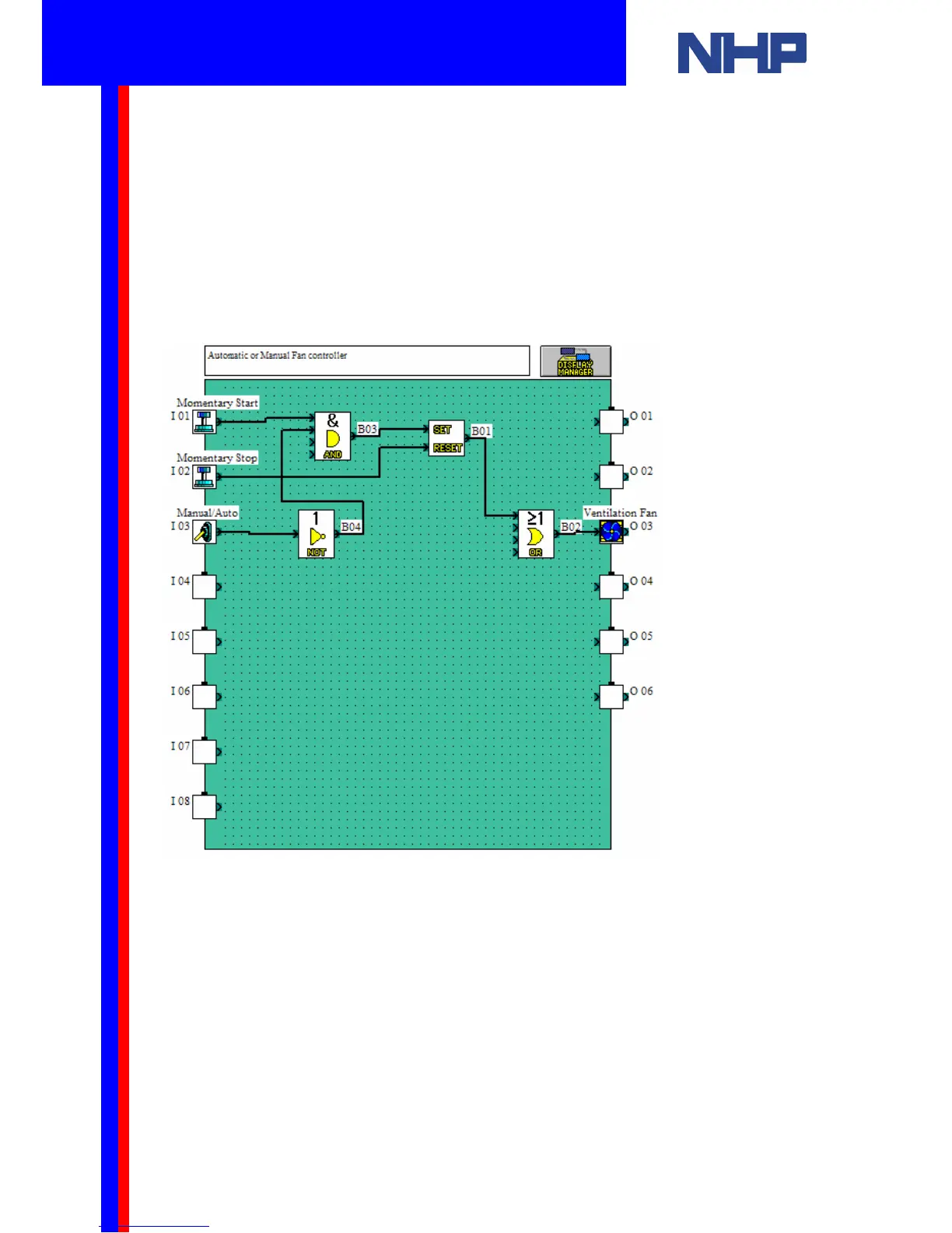
16. Paste it on the FBD, next to the Input 03 (B03)
17. Search for the “NOT” function block, and click on it
18. Paste it on the FBD, next to the Input 03 (B04)
19. Select the wiring tool by clicking on the “Wiring” toolbar
20. Connect the Input 01 to the first input of the “AND” function block (B03)
21. Connect the Input 03 to the second input of the “AND” function block (B03)
22. Connect the output of the “AND” function block (B03) to the “SET” point of the “SET
RESET” function block (B01)
Q u i c k S t a r t G u i d e
 Loading...


