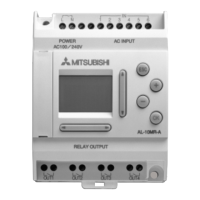
Do you have a question about the Mitsubishi alpha 2 and is the answer not in the manual?
Details the diverse functionalities and capabilities of the Alpha 2 series controllers.
Lists and describes the different models within the Alpha 2 series product line.
Provides physical dimensions and labels for each part of the controller.
Illustrates typical system configurations for the Alpha 2 series controllers.
Documents the evolution and changes across different versions of the Alpha 2 series.
Identifies the software required for programming the Alpha 2 series controllers.
Details the electrical power requirements and characteristics for the controllers.
Defines the electrical characteristics and requirements for input signals.
Details the electrical characteristics and capabilities of the output terminals.
Provides a summary of environmental and general electrical specifications.
Provides essential guidelines and precautions for safe and proper mounting.
Step-by-step instructions for mounting the main unit onto a DIN rail.
Instructions for installing the main unit directly onto a surface.
Guides the user through the process of attaching extension modules.
Key notes and safety precautions for performing electrical wiring.
Specifies recommended wire gauges and stripping lengths for terminals.
Instructions for correctly connecting AC and DC power supplies.
Details wiring procedures for AC power and input connections.
Details wiring procedures for DC power and input connections.
Guides wiring for relay and transistor output connections.
Diagrams showing terminal connections for various main unit models.
Diagrams illustrating terminal layouts for different extension modules.
Instructions for installing and removing the memory cassette.
Explains the purpose and use of the RS-232C communication cable.
Procedure for connecting and disconnecting the communication cable.
Describes the function of the GSM cable for modem connectivity.
Provides step-by-step instructions for installing the GSM cable.
Details on setting up modems for remote monitoring and maintenance.
Explains the role of the ASI-BD module in AS-interface networks.
Lists the hardware and software communication specifications.
Guides the user through wiring and installation of the ASI-BD module.
Details on setting slave addresses and troubleshooting AS-interface errors.
Explains the DCF77 function for automatic real-time clock setup.
Describes the necessary components and setup for DCF77 reception.
Lists the technical specifications for the DCF77 antenna and power pack.
Provides instructions for wiring the DCF77 antenna and controllers.
Step-by-step guide for configuring DCF77 settings using the controller display.
Details on how DCF77 decoding automatically starts and stops.
Methods for checking the validity and accuracy of received time data.
Explains the function of the AL2-2DA module for analog output signals.
Details the power, hardware, and software specifications.
Guides on proper wiring and installation of the analog output module.
Troubleshooting common errors related to the AL2-2DA module.
Describes the module for amplifying PT100 temperature input to analog signals.
Illustrates how the AL2-2PT-ADP module connects within a system.
Lists general, power, adjustment, and hardware specifications.
Provides instructions for wiring and installing the temperature adaptor module.
Guides on selecting Celsius or Fahrenheit for temperature readings.
Procedure for calibrating the offset value for temperature inputs.
Procedure for calibrating the gain value for temperature inputs.
Fine-tuning the offset calibration after initial adjustments.
Troubleshooting guide for errors related to temperature sensor inputs.
Explains the module for amplifying thermocouple inputs to analog signals.
Illustrates how the AL2-2TC-ADP module connects within a system.
Lists general, power, adjustment, and hardware specifications.
Provides instructions for wiring and installing the thermocouple adaptor module.
Guides on selecting Celsius or Fahrenheit for temperature readings.
Procedure for calibrating the offset value for thermocouple inputs.
Procedure for calibrating the gain value for thermocouple inputs.
Fine-tuning the offset calibration after initial adjustments.
Troubleshooting guide for errors related to thermocouple sensor inputs.
Defines the function of each key used for menu and program operation.
Lists system bits controlled by the system and user programs.
Details control bits that manage system functions and user interface.
Enumerates available function blocks for programming logic.
Guides on checking input status and resolving related display errors.
Guides on checking output status and resolving operation issues.
Troubleshooting steps when the Top Menu is not accessible.
Diagnoses reasons why the controller cannot switch to Run mode.
Addresses issues related to lost or inaccurate time data.
Explains the meaning of the '?' symbol on the display.
Troubleshooting steps for unresponsive operation keys.
Guides on resolving problems with the LCD display appearance.
Troubleshooting steps for memory cassette not being recognized.
Diagnoses issues with communication to the AS-interface master module.
Troubleshooting steps for communication failures with the programming software.
| Model | Alpha 2 |
|---|---|
| Communication Ports | RS-232, RS-485 |
| Expansion Modules | Yes |
| Type | Programmable Logic Controller |
| Input Voltage | 12-24V DC or 100-240V AC |
| Output Type | Relay, Transistor |
| Programming Language | Ladder Logic |
| Operating Temperature | -10 to 55°C |
| Storage Temperature | -20°C to 70°C |
| Analog Inputs | Optional with expansion |
| Analog Outputs | Optional with expansion |


