α
2 Simple Application Controllers
Wiring 4
ENG-24
4.6 Output Relay and Transistor Wiring
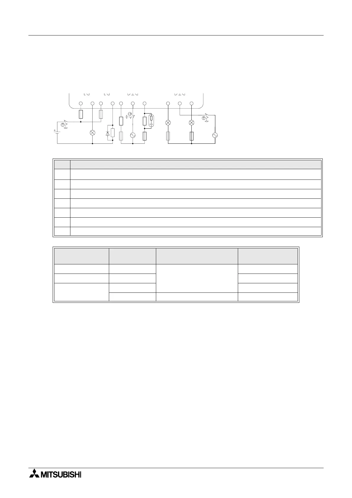
4.6.1 Relay Output Wiring Diagram main unit (AC and/or DC)
Figure 4.9: Relay Output Wiring Diagram main unit (AC and/or DC)
Table 4.9: Relay Output Wiring main unit (AC and/or DC)
Ref. Item Description
1
α2 main unit
2 Mutually exclusive outputs
3 Output devices
4 Circuit protection device (See Table 4.10)
5 Emergency stop
6 DC power supply
7 AC power supply
Table 4.10: Relay Output Circuit Protection Table
Model
Number of
Output
Max. Resistive Load
Circuit Protection
(Fuse)
AL2-10MR-* O01-O04
8A/common
≤ 10A / Circuit
AL2-14MR-* O01-O06 ≤ 10A / Circuit
AL2-24MR-*
O01-O04 ≤ 10A / Circuit
O05-O09 2A/point (4A/common) ≤ 3A / Circuit
OUT1
OUT2 OUT3 OUT4
OUT5 OUT6

 Loading...


