α
2 Simple Application Controllers
AL2-2DA (AL2-14MR-*, AL2-24MR-*) 11
ENG-57
ENG
11.3 Wiring & Installation
11.3.1 Installation
Caution
• Disconnect all terminals from the power supply before installing the AL2-2DA.
• Do not install in areas with: excessive or conductive dust, corrosive or flammable gas,
moisture or rain, excessive heat, regular impact shocks or excessive vibration.
• The
α2 Series Controller and AL2-2DA must be installed in a distribution box or a control
cabinet.
• Leave a minimum of 10 mm (0.40") of space for ventilation between the top and bottom
edges of the
α2 Series Controller and the enclosure walls.
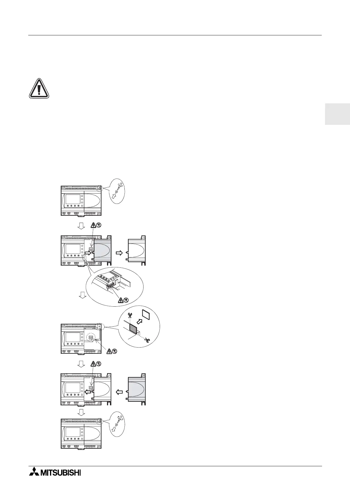
Figure 11.2: Installation
1) Release screw ‘A’ and keep.
2) Carefully remove the factory fitted expansion
port cover.
3) Cut away section ‘B’ from the
α2 series
controller main unit.
4) Attach the expansion module to the main unit.
5) Tighten screw ‘A’ to a torque of 0.4 N·m.
OUT1
OK
-
+
ESC
OUT3
9
RELAY
OUTPUT
65
OUT
8
OUT2 OUT4
7
DC INPUT
151413121110987654321(B)(A)
+-
24V DC
POWER
AL2-24MR-D
A
AL2-24MR-D
POWER
24V DC
-+
(A)(B)123456 789101112131415
DC INPUT
7
OUT4OUT2
8
OUT
56
OUTPUT
RELAY
9
OUT3
ESC
+
-
OK
OUT1
OUT1
OK
-
+
ESC
OUT3
9
RELAY
OUTPUT
65
OUT
8
OUT2 OUT4
7
DC INPUT
151413121110987654321(B)(A)
+-
24V DC
POWER
AL2-24MR-D
A
1)
2)
3)
4)
5)
AL2-24MR-D
POWER
24V DC
-+
(A) (B) 1 2 3 4 5 6 7 8 9 10 11 12 13 14 15
DC INPUT
7
OUT4OUT2
8
OUT
5
OUTPUT
RELAY
9
OUT3
ESC
+
-
OK
OUT1
AL2-24MR- D
POWER
24V DC
-+
(A)(B)123456 789101112131415
DC INPUT
7
OUT4OUT2
8
OUT
5
OUTPUT
RELAY
9
OUT3
ESC
+
-
OK
OUT1
6
B

 Loading...


