α
2 Simple Application Controllers
Wiring 4
ENG-23
ENG
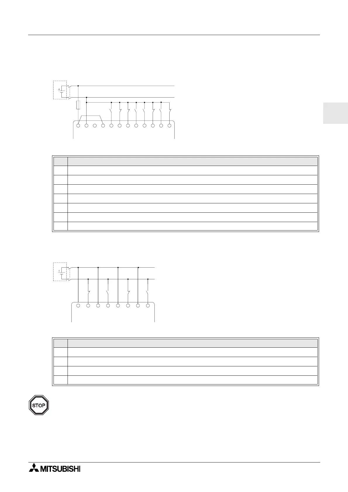
4.5.3 DC Power Supply and Sink (“-” Common) Input Wiring Diagram
Figure 4.7: DC Power Supply and Sink (”-” Common) Input Wiring Diagram
4.5.4 AL2-4EX Sink (“-” Common) Input Wiring Diagram
Figure 4.8: AL2-4EX Sink (”-” Common) Input Wiring Diagram
Note:
Each input terminal (EI1 - EI4) can be used as either Source input or Sink input.
Table 4.7: DC Power Supply and Sink (“-” Common) Input Wiring
Ref. Item Description
1
DC power supply, 24V DC
2 Circuit isolation device
3
Circuit protection device - Limit to 1.0 Amps
4
DC power terminals
5
Sink/Source input wiring terminals
6
Sensor input switches
7
Input terminals
Table 4.8: DC Power Supply and Sink (“-” Common) Input Wiring
Ref. Item Description
1
DC power supply, 24V DC
2 Circuit isolation device
3
Input terminals
4
Sensor input switches
+-
1
2
3
456
(A) (B)
78
INPUTS
EI1
(+)
EI1
(-)
EI2
(+)
EI2
(-)
EI3
(+)
EI3
(-)
EI4
(+)
EI4
(-)

 Loading...


